


10
SIGNAL GND
POWER
DATA10/100BASE-TMODERS-232C
MULTI
SCREEN OUT
SPOT
OUT
1
1
ALARM/REMOTE
OFF
ON
2
2
3
3
4
4
5
5
6
6
7
7
8
8
OUT
VIDEO
OUT
AUDIO
IN
IN
#1 #3
#0 #2 #4 #6 #9 $0
#5 #7 #8
$1 $2 $3
$4
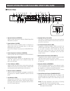
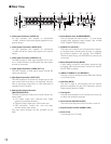
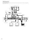
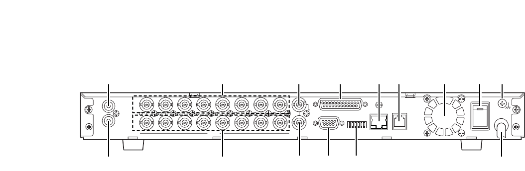
■ Rear View
#0 Audio Input Connector (AUDIO IN)
An RCA standard jack accepts an unbalanced
–10 dBV, 10 kΩ line input audio signal supplied from an
external device.
#1 Audio Output Connector (AUDIO OUT)
An RCA standard jack supplies an unbalanced
–10 dBV, 600 Ω line output audio signal to an external
device.
#2 Video Input Connector (VIDEO IN 1-8)
This BNC accepts a video signal supplied from a cam-
era. A 75 Ω termination is made unless the video output
terminal is connected.
#3 Video Output Connector (VIDEO OUT 1-8)
This BNC supplies a video signal looped through the
video input terminal.
#4 Spot Output Connector (SPOT OUT)
This BNC supplies a full-screen live image signal to the
spot monitor while recording or not recording. No play-
back or split image, setup menu, or OSD information is
supplied via this connector.
#5 Multi-screen Output Connector
(MULTISCREEN OUT)
This BNC provides the multi-screen monitor with the fol-
lowing video.
• Live image: single spot, multi-split spot, single
sequence, quad-split sequence
• Playback image: single spot, multi-screen spot
•OSD information: camera title, time and date,
recorder status, alarm status
The menu setup windows are also provided via this
BNC.
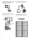
#6 Alarm/Remote Port (ALARM/REMOTE)
This port accepts the alarm inputs 1 – 8, and remote
controls while supplying status outputs. See ALARM
PORT CONNECTIONS for details.
#7 RS232C Port (RS-232C)
This 9-pin port is used to communicate with the person-
al computer when controlling the recorder, or updating
the firmware installed in the recorder. See CONNEC-
TIONS for cable wiring, and APPENDIX for protocol and
commands.
#8 Mode Setup DIP Switch (MODE)
A 6-bit switch is used for such system setups as disk
formatting, PSD chain termination, and so forth. See DIP
SW SETTING for details.
#9 10Base-T/100Base-T (10/100BASE-T)
This port is used to exchange control data with Ethernet
via an Ethernet Hub.
$0 Data Port (DATA)
This port is used to communicate with the external
devices compatible with the PSD (Panasonic Security
Data) protocol based on RS485.
$1 Cooling Fan
Prevents the temperature of the recorder from rising. Do
not block the ventilation openings.
$2 Power Switch (POWER ON OFF)
This switch turns the power of the recorder on and off.
$3 Signal Ground Terminal (SIGNAL GND)
$4 Power Cord
Is connected to an AC outlet.