6 - 5 6 - 5
MELSEC-GOT
6 PROGRAMMING
6.2 Sequence Program Example When Monitoring Using Dedicated Command Monitor
Method
The following system example is used to describe the sequence program in this
section. Refer to the CC-Link Master Module User's Manual regarding the sequence
program for the entire CC-Link system.
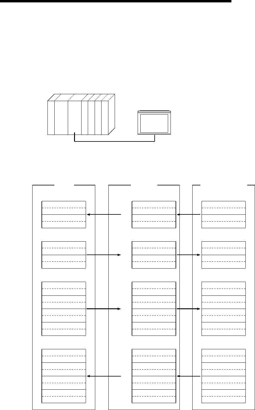
6.2.1 System configuration of the program example
QnA
CPU
Station No. : 1 station
Number of
stations occupied : 2 station setting
GOT
Master
unit
6.2.2 Relationship among the PLC CPU, master station buffer memory, and remote device
stations
Master station PLC CPU
GOT
(Remote device starion)
Address
Remote input (RX)
RX00 to RX0F
RX10 to RX1F
RX20 to RX2F
RX30 to RX3F
E0
H
E1
H
E2
H
E3
H
Address
Remote output (RY)
RY00 to RY0F
RY10 to RY1F
RY20 to RY2F
RY30 to RY3F
160
H
161
H
162
H
163
H
Address
Remote register (RWw)
(Write area)
RWw0
RWw1
RWw2
RWw3
1E0
H
1E1
H
1E2
H
1E3
H
RWw4
RWw5
RWw6
RWw7
1E4
H
1E5
H
1E6
H
1E7
H
Address
Remote register (RWr)
(Read area)
RWr0
RWr1
RWr2
RWr3
2E0
H
2E1
H
2E2
H
2E3
H
RWr4
RWr5
RWr6
RWr7
2E4
H
2E5
H
2E6
H
2E7
H
Remote input (RX)
RX00 to RX0F
RX10 to RX1F
RX20 to RX2F
RX30 to RX3F
Remote output (RY)
RY00 to RY0F
RY10 to RY1F
RY20 to RY2F
RY30 to RY3F
Remote register (RWw)
(Write area)
RWw0
RWw1
RWw2
RWw3
RWw4
RWw5
RWw6
RWw7
Remote register (RWr)
(Read area)
RWr0
RWr1
RWr2
RWr3
RWr4
RWr5
RWr6
RWr7
M0 to M15
M16 to M31
M32 to M47
M48 to M63
M100 to M115
M116 to M131
M132 to M147
M148 to M163
D100
D101
D102
D103
D104
D105
D106
D107
D200
D201
D202
D203
D204
D205
D206
D207


