


5 - 7 5 - 7
MELSEC-GOT
5 PRE-OPERATION SETTINGS AND PROCEDURE
5.5 Wiring Method
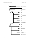
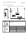
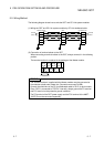
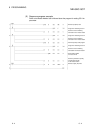
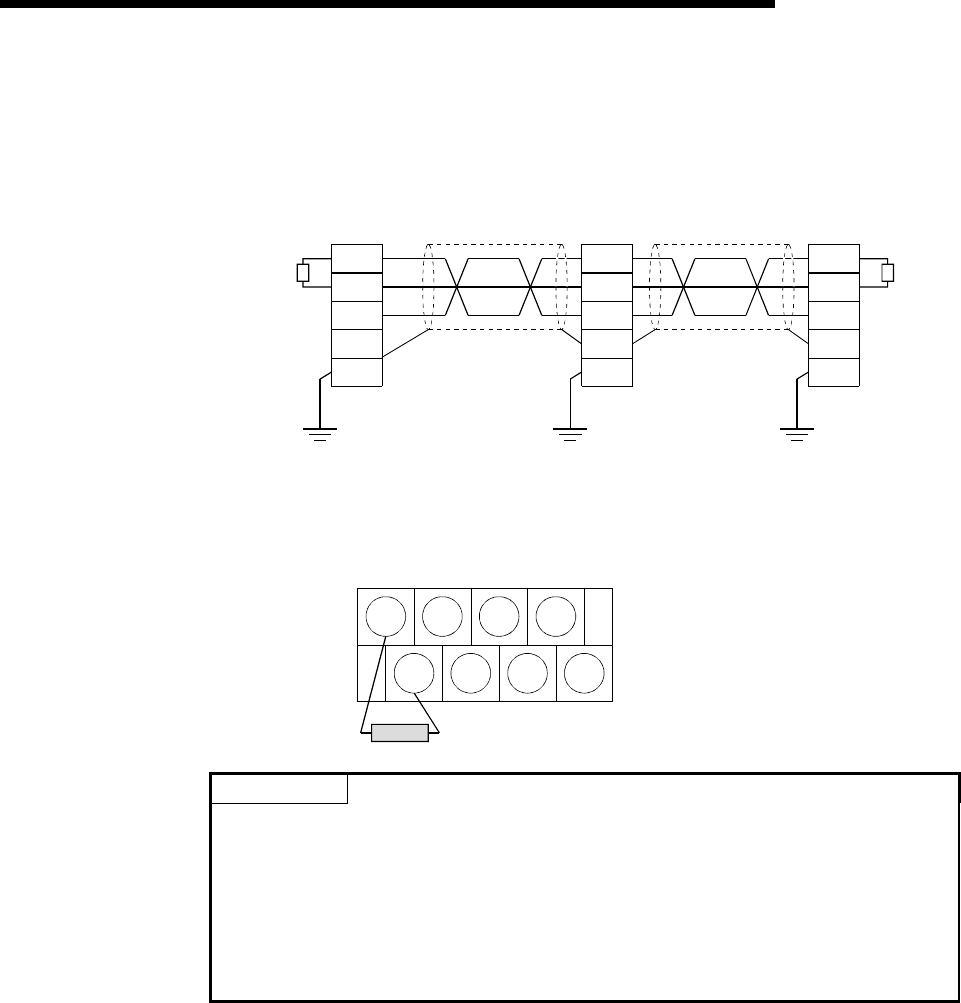
The following diagram shows how to wire the GOT and CC-Link system modules.
(1) Wiring the GOT and CC-Link system modules by CC-Link dedicated cable
DA
DB
DG
SLD
FG
DA
DB
DG
SLD
FG1
DA
DB
DG
SLD
FG
Master module GOT I/O module, etc.
T
erminal
r
esistor
CC-Link dedicated cable
Terminal
resistor
CC-Link dedicated cable
(Blue)
(Yellow)
(White)
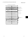
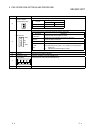
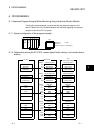
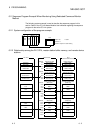
(2) Connection of terminal resistor to the GOT
When connecting a terminal resistor to the GOT, always connect it in the following
position.
The terminal resistor is contained in the package of the Master module.
DA DG NC NC
DB SLD FG1 NC
Terminal resistor
POINT
• The "terminal resistors" supplied with the Master module must be connected to
the modules at both ends of data link. (Connect them across DA-DB.)
• Connect the shield wire of the CC-Link dedicated cable to "SLD" of each module.
Since "SLD" is connected to "FG/FG1" internally, always ground the FG terminal
and FG1 terminal to the protective ground conductor.
• The FG terminal of the GOT power supply and the FG1 terminal of the A8GT-
J61BT15 must be connected separately.