6 - 3 6 - 3
MELSEC-GOT
6 PROGRAMMING
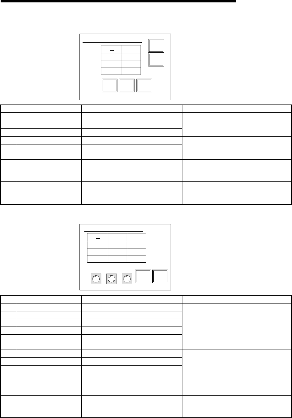
(3) Base screen No. 2 settings
Operating command screen
2)
1
Start-up
2
Start-up
3
Start-up
Main
screen
Production
situation
Parts
Line1
Line2
Line3
1)
3)
4)
5)
6)
7)
8)
No. Object Function to Be Set Setting Operation
1) Numerical input function Write device Wr0 to D200
2) Numerical input function Write device Wr1 to D201
3) Numerical input function Write device Wr2 to D202
Settings made to store the values entered with the
numerical input function into D200-D202.
4) Touch key function Bit alternate: X3 (RX3) to M3
5) Touch key function Bit alternate: X4 (RX4) to M4
6) Touch key function Bit alternate: X5 (RX5) to M5
Settings made to store the ON/OFF information
entered with the touch key function into M200-
M201.
7) Touch key function
Bit SET: X2 (RX2) to M2
Bit RST: X0 (RX0) to M0
Bit RST: X1 (RX1) to M1
Settings made to switch to base screen No. 3.
8) Touch key function
Bit SET: X0 (RX0) to M0
Bit RST: X1 (RX1) to M1
Bit RST: X2 (RX2) to M2
Settings made to switch to base screen No. 1.
(4) Base screen No. 3 settings
Production situation screen
3)
Main
screen
Production
situation
Parts A
1)
5)
2)
4)
6)
7) 8)
Line1
start-up
Parts B
Line2
start-up
Line3
start-up
9) 10) 11)
Line1
Line2
Line3
No. Object Function to Be Set Setting Operation
1) Numerical display function Monitor device: Ww1 (RWw1) from D101
2) Numerical display function Monitor device: Ww2 (RWw2) from D102
3) Numerical display function Monitor device: Ww3 (RWw3) from D103
4) Touch key function Monitor device: Ww4 (RWw4) from D104
5) Touch key function Monitor device: Ww5 (RWw5) from D105
6) Touch key function Monitor device: Ww6 (RWw6) from D106
Settings made to display the values stored in
D101-D106.
7) Lamp display function Monitor device: Y0 (RY0) from M100
8) Lamp display function Monitor device: Y1 (RY1) from M101
9) Lamp display function Monitor device: Y2 (RY2) from M102
Settings made to display on the GOT the line
operating statuses (ON/OFF) output to the remote
I/O station.
10) Touch key function
Bit SET: X1 (RX1) to M1
Bit RST: X0 (RX0) to M0
Bit RST: X2 (RX2) to M2
Settings made to switch to base screen No. 2.
11) Touch key function
Bit SET: X0 (RX0) to M0
Bit RST: X1 (RX1) to M1
Bit RST: X2 (RX2) to M2
Settings made to switch to base screen No. 1.


