


System Installation
20
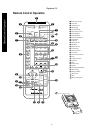
Signature 2.0
The 2.0 may also be connected to an optional, external
audio processor or decoder that accommodates digital
systems the 2.0 cannot handle internally. The analog
output connections from any external processor should
be made to the
6-CH Direct Inputs ¡
.
Video Inputs
Video source connections are made to either the
Composite Video
or
S-Video Inputs fl ‹
. When
connecting an audio/video device such as a VCR or DVD
it is a good idea to make all connections to the same
input number, (e.g.,
Video 1
,
Analog Audio 1
,
Digital Audio 1
) although any input number may be
used as long as you keep a note of which source is
connected to each numbered video input.
Once audio or video connections are made, they may
be matched with any other connection. They may also
be used with more than one input profile. For example,
the video output of a VCR or cable box may be used
both with the VCR’s own audio source for normal play-
back, but it may also be used with the 2.0’s built-in tuner
so that, for example, you may watch the video of a
sports broadcast along with the commentary from a
radio station using the simulcast feature.
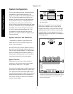
System and Accessory Inputs
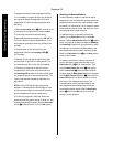
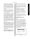
Assemble the AM loop antenna as shown below.
Connect it to the
AM Antenna Inputs ·
on the
rear panel.
Connect the FM antenna to the
FM (75 ohm)
connection
a
. The FM antenna may be an external roof
antenna, an inside powered or wire-lead antenna, or a
connection from a cable TV system. Note that if the
antenna or connection uses 300-ohm twin-lead cable,
you must use the 300-ohm to 75-ohm adapter supplied
with the unit to make the connection.
If the 2.0’s front panel remote sensor is blocked by
cabinet doors or other obstructions, an optional, external
IR sensor may be connected to the
IR Input ¶
. If you
are connecting multiple products to the same sensor, in
some applications the “IR In” may be connected to the IR
output of another compatible Harman Kardon product.
Consult your dealer or custom installer if you have
questions concerning the use of the IR input.
An
RS-232 Input §
is provided for use with custom
remote systems. Connections to this input jack should
ONLY be made by installers who are specially trained
in its use.
Output Connections
Audio Outputs
Using high-quality audio interconnect cables, connect the
Main Channel Audio Outputs ¢
to matching audio
inputs of your audio power amplifier for the left, center,
right, right surround and left surround channels. Connect
the power amplifier to the speakers in accordance with
the instructions provided by the amplifier and speaker
manufacturers.
Connections from the
Subwoofer Output ∞
should
be made to the mono line level input of a powered sub-
woofer or to the input of an audio power amplifier used
to power a passive subwoofer. In the event that the input
of the powered subwoofer has both left and right line
level inputs, consult the instructions provided with the
subwoofer to determine which input should be used, or
if any other special connection is required.
For Subwoofers with a stereo input only, it may be
necessary to use an optional “Y” cable. Consult the
Subwoofer’s instructions or your dealer for additional
information.
Video Outputs
Using high-quality video interconnect cables with a
coaxial-style construction, connect the
Composite
Video Main Output fi
and/or
S-Video Main
Output ¤
to the video or S-Video inputs of your TV,
projector, video monitor or other video display device
or processor.