


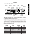
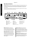

Rear Panel Connections
11
Signature 2.0
∞ Subwoofer Output
Connect this jack to the
line level mono input of an optional powered sub-
woofer, or the audio input of an external amplifier used
to drive a passive subwoofer. If you are using a passive
subwoofer that has both left and right inputs and no
indication of which to use for mono subwoofer inputs,
it is advisable that a “Y” cable be used so that the signal
is fed to both inputs.
§ RS-232 Control Port:
This jack is provided to
permit operation of the Signature 2.0 by computers or
home automation systems. The use of this control port
requires additional optional software and it is strongly
recommended that a Harman Kardon dealer be consulted
before any connections are made.
¶ IR Input:
If the 2.0’s front panel IR sensor is blocked
due to cabinet doors or other obstructions, an external IR
sensor may be used. Connect the output of the sensor to
this jack.
• IR Output:
This jack may be connected to other
compatible Harman Kardon products so that they
will receive infrared commands captured by the 2.0’s
remote sensor.
ª Trigger Output:
If a compatible Signature Series or
Harman Kardon audio power amplifier will be used with
the 2.0, connect the amplifier connection cable supplied
with the 2.0 between this jack and the “Trigger Input” of
the amplifier. When connected by a properly trained
dealer or installer, this output may also be used to control
other devices designed to accept a 6- to 12-volt “Power
On” trigger signal, such as projection television screens or
automatic blinds. The MAXIMUM current draw for all
circuits connected to this output is 150 milliamperes.
‚ AC Power Cord:
Connect this plug to an
unswitched, wall-mounted AC outlet.
⁄ S-Video Record Output:
Connect this jack to the
S-Video “REC-IN” input of a VCR.
¤ S-Video Main Output:
Connect this jack to the
S-Video input of the TV, video monitor, projector or
display that will be used to view the On-Screen Control
Menus of the 2.0 along with any selected S-Video input.
‹ S-Video Inputs:
Connect the output of S-Video
sources to these input jacks. Once the inputs have been
connected they may be assigned to any of the 2.0’s seven
source positions using the
Source Menu
(see figure
OSD-5 on page 27).
› Composite Video Record Output:
Connect this
jack to the composite video “REC-IN” input of a VCR.
fi Composite Video Main Output:
Connect this
jack to the composite video input of a TV set, video
monitor, projection television or other video display
device that will be used to view the On-Screen Control
Menus of the 2.0 along with the selected video input.
fl Composite Video Inputs:
Connect the output of
composite video sources to these input jacks. Once the
inputs have been connected they may be assigned to any
of the 2.0’s source positions using the
Source Menu
(see figure OSD-5 on page 27).
‡ Optical Digital Audio Inputs:
Connect the
Optical (TosLink) digital audio output of audio sources
to these jacks. Once the inputs have been connected
they may be assigned to any of the 2.0’s source
positions using the
Source Menu
(see figure
OSD-5 on page 27).
° Coax Digital Audio Inputs:
Connect the coax
digital audio output of audio sources to these jacks. Once
the inputs have been connected they may be assigned to
any of the 2.0’s source positions using the
Source
Menu
(see figure OSD-5 on page 27).
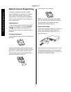
· AM Antenna Input:
Connect the AM loop antenna
supplied with the 2.0 to these terminals. An external AM
antenna may also be connected here.
a FM Antenna Input:
Connect an FM antenna
to these terminals. Note that the supplied 300-ohm to
75-ohm adapter is required for connections from twin-
lead dipole antennas.