


REAR-PANEL CONNECTIONS 9
REAR-PANEL CONNECTIONS
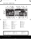
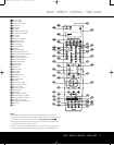
0 Preamp Outputs: Connect these jacks to an
optional, external power amplifier for applications
where higher power is desired.
1 Subwoofer Output: Connect this jack to the line-
level input of a powered subwoofer. If an external sub-
woofer amplifier is used, connect this jack to the sub-
woofer amplifier input.
2 Tape Outputs: Connect these jacks to the
Record/Input jacks of an audio recorder.
3 A-BUS Connector:
Connect this jack to optional
A
-BUS
®
-
certified products to extend the multiroom
capabilities of your AVR 445. See page 19 for more
information on A-BUS.
4
Tape Inputs: Connect these jacks to the Play/Out
jacks of an audio recorder.
5 Surround Speaker Outputs: Connect these out-
puts to the matching + and – terminals on your sur-
round channel speakers. In conformance with the CEA
color-code specification, the blue terminal is the posi-
tive (+) terminal that should be connected to the red
(+) terminal on the Surround Left speaker with older
color-coding, while the gray terminal should be con-
nected to the red (+) terminal on the Surround Right
speaker with the older color-coding. Connect the black
(–) terminal on the AVR to the matching black nega-
tive (–) terminals for each surround speaker. (See
page 17 for more information on speaker polarity.)
6 CD Audio Inputs: Connect these jacks to the
left/right analog audio output of a compact disc player
or CD changer or other audio source.
7 Front Speaker Outputs: Connect these outputs
to the matching + or – terminals on your left and right
speakers. When making speaker connections, always
make certain to maintain correct polarity by connecting
the color-coded (white for front left and red for front
right) (+) terminals on the AVR 445 to the red (+)
terminals on the speakers and the black (–) terminals
on the AVR 445 to the black (–) terminals on the speakers.
See page 17 for more information on speaker polarity.
8 Multiroom Audio Outputs: Connect these jacks
to the optional exter
nal audio power amplifier and
video distribution system that delivers the source
selected for multizone distribution.
9 Digital Media Player (DMP) Input:
With the
AVR 445 turned off, connect the optional
Harman Kardon to this connector. Once
this is done and with a compatible iP
od
®
(optional)
docked in The Bridge, selecting the The Bridge/DMP
input allows you to play audio from the iPod and view
navigation menus on the AVR’s front panel and any
video display connected to the
A
VR. Y
ou may control
the iPod’s functions and select tracks using the
⁄/¤/‹/›n
©
, Set
F
œ
and Transport
GIJ
π
buttons. See page 39 for more
information.
A Fan Vents: These ventilation holes are the output
of the AVR 445’s airflow system. To ensure proper
operation of the unit and to avoid possible damage to
d
elicate surfaces, make certain that these holes are
n
ot blocked and that there is at least 3 inches of open
space between the vent holes and any wooden or
fabric surface. It is normal for the fan to remain off at
most normal volume levels. An automatic temperature
s
ensor turns the fan on only when it is needed.
B Full Carrier IR Output: The output of this jack
is the full signal received at the
Remote Sensor
Window
^ or input through the IR Input F includ-
ing the carrier frequency that is removed from signals
at the
IR Output C.
Use this output to extend IR
signals to the input of compatible products either by
direct connection or through the use of optional,
external IR “blasters”. If you are in doubt as to which
of the IR Output jacks to use, we recommend that
you consult with your dealer or installer, or check
with the manufacturer of the external equipment
you wish to control.
C IR Output: This connection permits the IR sensor
in the receiver to serve remote controlled devices with
“stripped carrier.” Connect this jack to the “IR IN” jack
on compatible Harman Kardon equipment.
D Center Channel Speaker Outputs: Connect
these outputs to the matching + and – terminals on
your center channel speaker. In conformance with the
CEA color-code specification, the green terminal is the
positive (+) terminal that should be connected to the
red (+) terminal on speakers with the older color-cod-
ing. Connect the black (–) terminal on the AVR to the
black negative (–) terminal on your speaker. (See
page 17 for more infor
mation on speaker polarity.)
E Surround Back/Multiroom Speaker Outputs:
These
speaker ter
minals are normally used to power
the surround back left/surround back right speakers
in a 7.1-channel system.
However
,
they may also be
used to power the speakers in a second zone, which
will receive the output selected for a multiroom system.
To change the output fed to these terminals from
the default of the Surround Back speakers to the
Multiroom Output, you must change a setting in the
Multiroom menu of the OSD system. See page 44 for
more information on configuring this speaker output.
In normal surround system use, the brown and black
ter
minals are the surround back left channel positive
(+) and negative (–) connections and the tan and
black terminals are the surround back right positive
(+) and negative (–) terminals. For multiroom use,
connect the brown and black SBL ter
minals to the
red and black connections on the left remote zone
speaker and connect the tan and black SBR terminals
to the red and black ter
minals on the right remote
zone speaker.
F IR Input: If the AVR 445’s front-panel IR sensor
is blocked due to cabinet doors or other obstruc-
tions, an external IR sensor may be used. Connect
t
he output of the sensor to this jack.
G Switched AC Accessory Outlet: This outlet may
be used to power any device you wish to have turned
on when the AVR 445 is turned on with the
Standby/
O
n Switch
1.
IMPORTANT NOTE: The power consumption of
any device connected to the accessory outlet should
not exceed 100 watts. Never connect high-power
d
evices such as amplifiers or video displays to the
accessor
y
outlet.
H Trigger Output: Connect this jack to the “Trigger
In” jack of an optional external component such as an
audio power amplifier that you want to be controlled
to mirror the power state of the AVR 445. When this
connection is used, the AVR 445 will automatically
send a low-voltage signal to the connected device that
turns it on when the AVR 445 is on, and off when the
AVR 445 is placed in the Standby mode. The con-
nected component must respond to a 6-volt presence
as the control signal.
I AC Power Cord Socket: Connect the AC power
cord here when the installation is complete. To ensure
safe operation, use only the power cord supplied with
the unit. If a replacement is required, it must be of the
same type and capacity.
J RS-232 Port: This jack may be used to control
the AVR 445 over a bidirectional RS-232 serial
control link to a compatible computer or programmable
remote control system. Due to the complexity of
programming RS-232 commands, we strongly
recommend that connections to this port for
control purposes be made by a trained and qualified
technician or installer.
K HDMI Output: Connect this jack to the HDMI
input on a compatible HDMI-equipped video display
.
L HDMI Inputs: Connect the HDMI output of video
sources such as a DVD player, set-top box or HDTV
tuner to either of these jacks.
M Component Video Monitor Outputs: Connect
these outputs to the component video inputs of a
video display.
N Multiroom IR Input: Connect the output of
an IR
sensor in a remote room to this jack to operate the
A
VR 445’s multiroom control system.
O Component Video Inputs: These inputs may be
used with any source device that is equipped with
analog component video outputs, as assigned through
the
IN/OUT
SETUP
menu.
See page 23
for more infor
mation on configuring the component
video inputs.
The
Bridge
TM
The
Bridge
TM
AVR445 OM 6/23/06 3:13 PM Page 9