


SYSTEM CONFIGURATION
SYSTEM CONFIGURATION 21
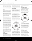
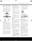
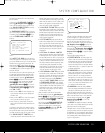
cle. A good way to visualize proper surround speaker
positioning for 7.1 is to place the speakers directly to
the left and right of the ears of someone sitting in the
p
rime listening spot. The two speakers should ideally
f
ace toward each other.
The additional Surround Back Left/Right speakers are
placed at about 150 degrees on the circle, pointing
i
nward, toward the listening area. The easiest way to
visualize the placement of these speakers is to place
the surround back left speaker directly opposite the
right front speaker and to place the surround back left
speaker directly opposite the left front speaker.
7.1 Placement Diagram
Subwoofer Placement
Since subwoofers produce nondirectional sound, they
may be placed almost anywhere in a room. Actual
placement should be based on room size and shape
and the type of
subwoofer
used. One method of find
-
ing the optimal location for a subwoofer is to begin by
placing it in the front of the room, about six inches
from a wall, or near the front corner of the room.
Another method is to temporarily place the subwoofer
at your normal listening position, and then walk
around the room until you find a spot where the sub-
woofer sounds best. Place the subwoofer in that spot.
Y
ou should also follow the instructions of the
subwoofer’s
manufacturer
,
or you may wish to experiment with
the best location for a subwoofer in your particular
listening room.
For more information on subwoofer placement, as well
as a variety of topics relating to audio and home the
-
ater, visit the Technology section of our Web site at
www.harmankardon.com. Links are provided there to
infor
mative white papers written by the acoustic and
electronics experts at Harman Kardon and at our par-
ent company,
Har
man International Industries, Inc.
NOTES ON SPEAKER PLACEMENT:
1. The limitations of your listening room, including the
placement of walls and furniture, may make it diffi-
cult to follow the speaker placement suggestions
shown above. Depending on the specific layout of
the room, here are some ways to compensate for
unusual conditions:
• Try to follow the suggested placement, but move
the speakers within a few feet from the preferred
locations.
•
Regardless of where they are placed, always try
to make certain that the main surround speakers
are the same distance from the front speakers.
(For example, try not to have the right surround
speaker further back into the room than the left
surround speaker.)
• If it is not possible to wall-mount or place speak-
ers on a shelf, consider the use of optional floor
stands, available for many speakers.
2. When using ceiling-mounted in-wall speakers, fol-
low the same guidelines shown for conventional
floorstanding or shelf-mounted speakers.
System Setup
Once the speakers have been placed in the room and
connected, the remaining steps in the setup process
are to assign input and output connections, make any
video or audio adjustments, select a surround mode,
program the AVR 445’s bass management system for
the type of speakers used in your system, calibrate
the output levels and set the delay times used by the
surround sound processor.
Although it is necessary to assign input/output settings
and surround mode choices manually
,
we recommend
that you take advantage of the power and precision of
EzSet/EQ to automatically select and enter the settings
for all other audio parameters
. This will not only
save
you time; it will ensure that your room is calibrated
and
equalized with an accuracy not possible when these
settings are made manually.
You are now ready to power up the AVR 445 to begin
these final adjustments.
1. Make certain that the AC power cord is firmly
inserted into the
AC
Power Cord Socket
I
and plug the cord into an unswitched AC outlet.
T
o maintain the unit’
s safety rating, DO NOT
substitute the power cord for one with lower
current capacity.
2.
Press the
Main P
o
wer Switch
A located
behind the
Front-Panel Control Door 9 in
until it latches and the word “OFF” on the top of
the switch disappears inside the front panel. Note
that the illumination around the
Standby/On
Switch
1 will turn amber, indicating that the
unit is in the Standby mode.
3. Carefully remove the protective plastic film from
the front-panel lens. If left in place, the film will
prevent proper operation of the remote control.
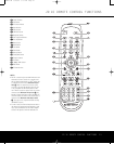
4. Install the four supplied AAA batteries in the
main remote as shown. Be certain to follow the
(+) and (–) polarity indicators that are in the
battery compartment. (The ZR10 remote
r
equires two AAA batteries.)
5. Turn the AVR 445 on either by pressing the
Standby/On Switch 1 on the front panel, or
via the remote by pressing the
Power On Button
b, the AVR Selector e
ç
or any of the
Input Selectors
3Xh
ç∂ƒ
≠®
on the remote. The lighting around the
Standby/On Switch 1 will turn blue to confirm
that the unit is on.
Using the On-Screen Display
When making the following adjustments, you may
find it easier to use the AVR 445’s on-screen display
system. These easy-to-read displays give you a clear
picture of the current status of the unit and make it
easy to see which speaker, delay, input or digital
selection you are making.
To view the on-screen menus, make certain that you
have made a video connection to the appropriate
matching input of your
TV or projector
. In order to view
the AVR 445’s displays, the correct video source must
be selected on the video display. On-screen menus
may be viewed through component,
S-video or com-
posite video connections, but they are not available
when an HDMI source is selected as the input or
through the
HDMI Output K.
IMPORTANT NOTE: When viewing the on-screen
menus using a CR
T
-based projector, plasma display or
direct-view CRT monitor or television, it is important that
they not be left on for an extended period of time
.
The
constant display of a static image such as these menus
may cause the image to be permanently “burned into”
the projection tubes, plasma screen or CRT display.
This type of damage is not covered by the
A
VR 445
warranty and may not be covered by the projector/TV
set’s warranty.
The AVR 445 has two on-screen display modes,
“Semi-OSD”
and “Full-OSD.” When making configura-
tion adjustments
,
it is recommended that the full-OSD
mode be used. This will place an easily viewed list of
the available options on the screen.
Center Speaker
V
ideo Screen
Front Right
Speaker
F
ront Left
Speaker
S
ide Surround
Left Speaker
Back Surround
Left Speaker
Side Surround
R
ight Speaker
B
ack Surround
Right Speaker
90°
150°
90°
1
50°
3
0° 30°
AVR445 OM 6/23/06 3:13 PM Page 21