


SYSTEM CONFIGURATION 23
SYSTEM CONFIGURATION
When the desired auto-poll setting is entered, press
the
⁄/¤ Navigation Button D
©
to move to
the next line.
When the cursor is at the
VIDEO IN-PORT
line, you are able to select an alternative to the default
input setting for the video input associated with any
s
ource except HDMI 1 and HDMI 2. For the Video 1
a
nd Video 4 inputs, the factory default of
A
UTO
w
ill
select either composite or S-video, depending on
which has an active signal. For the Video 2, Video 3
and DVD inputs, the
AUTO setting will normally
s
elect the default component input, but if it is not
in use, the system will revert to a composite or
S-video output if either one is active. You may set
COMPONENT INPUT to OFF if you
aren’t using component video, and the AVR will not
select the component video inputs.
To have the AVR always look to a specific source con-
nection when an input is selected, make certain that
the on-screen cursor is pointing to the
VIDEO
IN-PORT
line; then press the ‹/› Navigation
Buttons
D
©
until the name of the desired input
appears. Note that this setting is not available when
the HDMI inputs are selected. The choice of available
inputs may vary according to whether an audio-only
source (such as the tuner, CD or tape) or an audio/
video source (such as Video 1–Video 4 or DVD) is
selected.
When the desired video input setting has been made,
press the
⁄/¤ Navigation Buttons D
©
to
move to the next line.
If your system includes any sources that are equipped
with Y/Pr/Pb component video outputs, the AVR 445
is able to switch them to send the proper signals to
your video display. Each of the
Component Video
Inputs
O is assigned to a default source
,
as shown
in the table in the Appendix, but if you have connected
your system differently than the factory settings, you
may select any of the three inputs for any source
except the HDMI inputs or the Tuner. If you do not
need to change these defaults, press the
¤
Na
vigation Button
D to go to the next setting
.
T
o change the
Component Video
assignment,
first
make certain that the cursor is pointing to the
COMPONENT INPUT line on the menu
screen,
and then press the
‹/› Na
vigation Button
D
©
until the desired input is highlighted.
When the desired component input has been selected,
or component video has been disabled by selecting
OFF
, press the ¤ Navigation Button D
©
to go to the next setting.
At the
VIDEO PROCESS line, you are able
to select whether video for
mat conversion is to be
used with the input source being configured. If you
do not need to change the setting, simply press the
⁄/¤ Navigation Buttons D
©
to continue
.
T
he default setting of
V
-CONVERSION
w
ill
output the incoming video in one of the following ways,
depending on the input source.
•
A standard-definition (480i) analog signal (composite,
S-video or component) will be converted so that it is
available at its input resolution, at the standard com-
posite, S-video or component analog video outputs.
The signal will also be available at the record outputs.
• An analog component high-definition signal will
be output at its input resolution as an analog com-
ponent signal, but not through the analog composite
or S-video monitor, or HDMI or record outputs.
• HDMI input signals, regardless of their resolution, will
be output through the
HDMI outputs only.
The
BYPASS setting will not apply any video
conversion to the incoming video signal, but it will
output it in one of the following ways
, depending on
the input source.
• Analog signals (composite, S-video or component)
will output only in the resolution and format that
matches the input for both the main “Monitor” con-
nection as well as for the record outputs.
• HDMI input signals, regardless of their resolution, will
be output through the HDMI outputs only.
After any needed change to the video conversion set-
ting has been made, press the
⁄/¤ Navigation
Buttons
D
©
to move to the next line.
At the
A/V SYNC DELAY line, you are able
to enter a setting that delays the audio output slightly
behind the video so that the loss of lip sync that may
occur due to digital video processing in the transmis-
sion of a program, in the playback unit or in the dis-
play is corrected.
This lack of lip sync is not a fault of
the sources;
rather
,
it is a by-product of video signal
processing. In most cases, we recommend that the
delay adjustment be made using the direct-access
controls on the remote so that you may more accu-
rately adjust the delay while viewing the on-screen
image
, following the instructions shown on page 30,
but you may also make it here using the menu sys-
tem. As the amount of delay needed may var
y from
one source to another, we strongly recommend that
you adjust it for each input.
To adjust the A/V sync delay time from the
IN/OUT SETUP menu, make certain that the
cursor is pointing to the
A/V SYNC DELAY
line, and then press the ‹/› Navigation Buttons
D
©
until the desired amount of delay is applied
so that the on-screen video matches the audio.
When all configuration adjustments on this menu
screen have been made, press the
⁄/¤ Navigation
Buttons
D
©
until the on-screen cursor is point
-
ing to
PAGE
2
and then press the Set Button
p
œ
to move to the second screen of input/out-
put settings. If all settings for input configuration are
complete, press the
⁄/¤ Navigation Buttons
D
©
until the on-screen cursor is pointing to
M
ASTER MENU
a
nd then press the
S
et Button
p
œ
t
o return to the main menu screen.
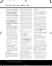
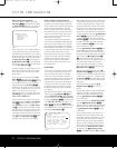
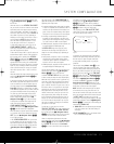
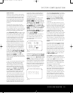
The second page of the
IN/OUT SETUP
menu (Figure 3) allows you to further configure the
A
VR 445 for special custom features.
Figure 3
An exclusive Harman Kardon feature is the ability to
switch the front-panel analog audio/video jacks from
their normal use as inputs to output connections
so that portable recording devices may easily be
connected.
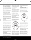
The front-panel analog
Video 4 Jacks N are nor-
mally set as inputs for use with camcorders, video
games and other portable audio/video products, but
they may be switched to outputs. First, make certain
that you are at the second page of the
IN/OUT
SETUP
menu. Press the
¤
Navigation Buttons
D
©
until the cursor points to the VIDEO 4
line. Press the
‹
/
›
Navigation Buttons D
©
so that the word OUT is highlighted. The Input/
Output Status Indicator
M between the S- and
composite video jacks will turn red, indicating that the
analog Video 4 jacks are now record outputs.
NOTE: Selection of the front-panel jacks as outputs
will remain effective as long as the
A
VR
445 is on.
Once the unit is tur
ned off
,
the jacks will revert to their
normal use as inputs when the unit is turned on again.
The
REC
OUT
line enables you to select the
audio output at the analog record outputs for the input
source being configured. Press the
‹
/
›
Navigation
Buttons
D
©
to choose one of the following (the
default setting is
ANALOG):
•
ANALOG selects an unprocessed pass-through
of an analog source and is the default setting for
most inputs.
•
DSP DOWNMIX selects a two-channel down-
mix of a multichannel digital input.
* IN/OUT SETUP *
VIDEO 4 :IN OUT
REC OUT :ANALOG
MASTER MENU PAGE 1
➔
AVR445 OM 6/23/06 3:13 PM Page 23