


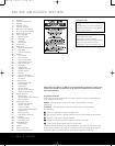
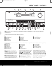
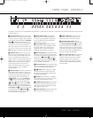

FRONT-PANEL CONTROLS
6 FRONT-PANEL CONTROLS
4 T
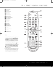
uning Selector:
P
ress the left side of the button
to tune lower-frequency stations and the right side of
the button to tune higher-frequency stations. When
the tuner is in the
MANUAL/MONO mode,
e
ach tap of the Selector will increase or decrease the
frequency by one increment. When the tuner receives
a signal strong enough for adequate reception,
MANUAL TUNED will appear in the Lower
D
isplay Line
$ a
nd in the on-screen display. When
t
he tuner is in the
A
UTO/STEREO
m
ode,
press the button once, and the tuner will scan for a
station with acceptable signal strength. When the
next higher- or lower-frequency station is tuned, the
frequency scan will stop and the
Lower Display Line
$ and the on-screen display will indicate AUTO
TUNED
. When an FM stereo station is tuned, the
display will read
AUTO ST TUNED. See page
39 for more information on using the tuner. When an
XM Ready module is connected and activated, and
when there is sufficient signal strength for the XM
system to operate, pressing this button will also
change the XM Radio channel.
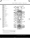
5 Tuner Band Selector: Pressing this button will
automatically switch the AVR 445 to the Tuner mode.
Pressing it again will select the AM or FM frequency
band, or XM Radio. (See page 39 for more informa-
tion on the tuner.)
6 Preset Station Selector: Press this button to
scroll up or down through the list of stations that have
been entered into the preset memory. (See page 39
for more information on tuner programming.)
7 Input Source Selector: Press this button to
change the input by scrolling up or down through the
list of input sources
.
8 Tuning Mode Selector: Press this button to select
Auto or Manual tuning. When the button is pressed so
that
AUTO/STEREO appears in the Upper
Display Line
#,
the tuner will search for the next
station with an acceptable signal when the
T
uning
Selector
4
M
π
is pressed. When the button is
pressed so that
MANUAL/MONO appears in the
Upper Display Line #, each press of the Tuning
Selector
4
M
π
will increase the frequency
. (See
page 39 for more information on using the tuner.)
This button may also be used to switch between Stereo
and Mono modes for FM radio reception. When weak
reception is encountered, select the Manual/Mono
t
uning mode. Press and hold again to switch back to
S
tereo mode. (See pages 39 for more information on
using the tuner.)
When an optional XM Connect & Play module is con-
nected and activated, and when there is sufficient sig-
nal strength for the XM system to operate, this button
has a different set of functions than when traditional
AM or FM radio is in use. See page 39 for more infor-
mation on XM Radio operation.
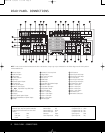
9 Front-Panel Door: To open the door so that the
front-panel jacks and controls behind this door may be
accessed, gently pull the door down and toward you,
using either upper corner of the door.
) Volume Control: Turn this knob clockwise to
increase the volume, counterclockwise to decrease the
volume. If the AVR 445 is muted, adjusting the volume
control will automatically release the unit from the
silenced condition.
! Input Indicators: One of these indicators will light
to identify the currently selected input. Note that the
entire list will light briefly each time the unit is turned
on, as a test.
@ Speaker/Channel Input Indicators: These indi-
cators are multipurpose, indicating both the speaker
type selected for each channel and the incoming data-
signal configuration. The left, center, right, right surround
and left surround speaker indicators are composed of
three boxes, while the subwoofer is indicated by one
box. The center box lights when a “small” speaker is
selected, and the two outer boxes light when “large”
speakers are selected. When none of the boxes are
lit for the center, surround or subwoofer channels, no
speaker has been assigned that position. The letters
inside each box display the active input channels. For
standard analog inputs, only the L and R will light, indi-
cating a stereo input. For a digital source, the indicators
will light to display the channels being received at the
digital input. When the letters flash, the digital input has
been interrupted.
(See page 38 for more infor
mation on
the Channel Indicators.)
# U
pper Display Line:
D
epending on the unit’s
status, a variety of messages will appear here. In
normal operation, this line will show the current input
source and identify whether an analog or digital input
i
s in use. When the tuner is selected as the input, this
line will identify the station as AM or FM and show the
frequency and preset number, if any.
When an XM Connect & Play module is connected
and activated, and when there is sufficient signal
strength for the XM system to operate, the XM chan-
nel number and signal strength will appear here.
$ Lower Display Line: Depending on the unit’s
status, a variety of messages will appear here. In nor-
mal operation, the current surround mode will appear
on this line. When an XM Ready module is connected
and activated, and when there is sufficient signal
strength for the XM system to operate, a variety of
messages and information, including the XM channel
title name, the current artist and track title, the XM
Radio channel category and, when available, local
traffic and weather information, will appear here.
% Surround Mode Indicators: One of these
indicators will light to show the surround mode in
use. Depending on the specific combination of input
sources and surround mode selected, more than
one indicator may light. (See page 36 for more
information.)
^ Remote Sensor Window: The sensor behind
this window receives infrared signals from the remote
control. Aim the remote control at this area, and do not
block or cover it unless an external remote sensor
is installed.
AVR445 OM 6/23/06 3:13 PM Page 6