


FRONT-PANEL CONTROLS
FRONT-PANEL CONTROLS
7
T
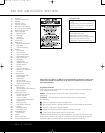
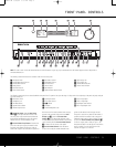
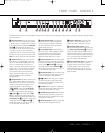
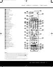
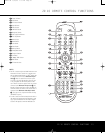
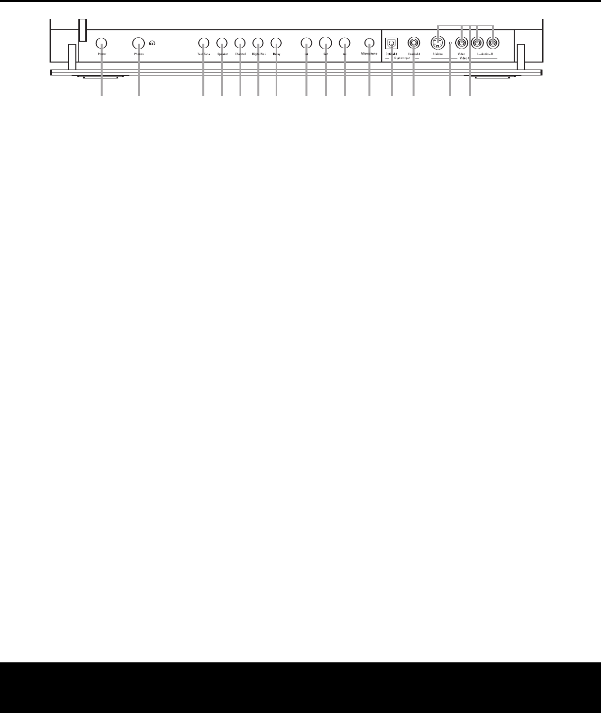
he following controls and jacks are located behind the front-panel door. To open the door, place the edge of a finger on the left or right edge of the panel and gently swing the
door down toward you.
A Main Power Switch: Press this switch to apply
power to the AVR 445. When the switch is pressed
in, the unit is placed in a Standby mode, as indicated
by the amber illumination surrounding the
Standby/On
Switch
1. This button MUST be pressed in to
operate the unit. To turn the unit off and prevent the
use of the remote control, this switch should be
pressed until it pops out from the front panel so that
the word “OFF” may be read at the top of the switch.
NOTE: This switch is normally left in the “ON” position.
B Headphone Jack: This jack may be used to lis-
ten to the AVR 445’s output through a pair of head-
phones. Be certain that the headphones have a stan-
dard 1/4" stereo phone plug, or that you use an
adapter, as needed, to convert the plug on your head-
phones to the 1/4" jack used on the AVR. When the
headphone jack is in use, the main room speakers
will automatically be turned off and the unit will
output a standard stereo signal. You may also use
the Dolby Headphone mode for an enhanced
listening experience.
C Tone Mode Button: This button controls the tone
mode settings, enabling adjustment of the bass and
treble boost/cut. You may also use it to take the tone
controls
out of the signal path completely for “flat”
response. The first press of the button displays a
TONE MODE message in the Lower Display
Line
$ and in the on-screen display. To take the
controls out of the signal path, press either of the
‹/› Buttons H until the display reads TONE
OUT
. To change the bass or treble settings, press
the button again until the desired option appears in the
Lower Display Line $ and in the on-screen display
and then press either of the
‹/› Buttons H to
enter the desired boost or cut setting. See page 35
for more information on the tone controls.
D Speaker Selector Button: Press this button
to begin the process of manually configuring the
AVR 445 for the type of speakers it is being used
with. For complete information on configuring the
speaker settings, see page 29.
E Channel Adjust Selector: Press the button to
begin the process of manually adjusting the channel
level outputs using the source currently playing
through your AVR. For complete information on
adjusting the channel output level, see page 41.
F Digital Input Selector: Press this button to begin
the process of selecting a digital source for use with
the currently selected input. Once the button has been
pressed, use the
‹/› Buttons H to choose the
desired input and then press the
Set Button I to
enter the setting into the unit’s memory. See page 35
for more information on digital audio.
G Delay Adjust Selector: Press this button to begin
the process of adjusting the delay settings. See page
30 for more information on delay adjustments.
H‹/› Buttons: When making system configura-
tion changes using the front-panel controls, press
these buttons to scroll through the available choices
for the option being adjusted.
I Set Button: When making system configuration
changes using the
front-panel controls, press this but-
ton to enter a setting into the unit’s memory.
J EzSet/EQ Microphone Jack: Before starting the
EzSet/EQ automated setup process, plug the micro-
phone into this jack.
The microphone does not need
to be plugged in at other times.
K Optical 4 Digital Input: Connect the optical digital
output of an audio or video product to this jack.
L Coaxial 4 Digital Input: Connect the coaxial
digital output of a digital audio product such as a
portable audio player or video game to this jack.
M Input/Output Status Indicator: This LED
indicator will normally light green to show that the front-
panel
Video 4 Input/Output Jacks N are operating
as inputs
. When these jacks are configured for use as
outputs, the indicator will turn red to show that the jack
may be used as an output for recording. (See pages 22
and 40 for more information on configuring the front-
panel jacks as outputs, rather than inputs.)
N Video 4 Input/Output Jacks: These audio/video
jacks may be used as either inputs or outputs for
temporary connection to video games or portable
audio/video products such as camcorders and
portable audio players. (See pages 22 and 40 for
more information on switching these jacks between
inputs and outputs.)
A
B
D
E
F
G
H H
I
J K LN
M
C
A
VR 445
XMFMAM
USB
DMP
TAPE
8CH
6CH
DVD
DIGITAL PLUS
PRO LOGIC IIx
HEADPHONE
VIRTUAL SPEAKER
57CH. STEREO
DIRECT
DSP
SURR. OFF
CDMI
HDMI 12
VID 34
VID 12
AVR445 OM 6/23/06 3:13 PM Page 7