


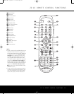
Making Configuration Adjustments
T
he full-OSD system is available by pressing the
OSD Button U
∫
. When this button is pressed,
t
he
M
ASTER MENU
(
Figure 1) will appear, and
adjustments are made from the individual menus.
Figure 1
The semi-OSD system is also available, allowing you
to make adjustments directly, by pressing the appro-
priate buttons on the front panel or remote control for
the specific parameter to be adjusted. For example, to
change the digital input for any of the sources, press
the
Digital Select Button o and then press the
⁄
/
¤
Navigation Button
n
to scroll through the
list of options as they appear in the on-screen display
or in the
Lower Display Line $.
Semi-OSD messages are available only when a 480i
input source is being viewed. They are not available
when a 480p, 720p or 1080i source or an HDMI
input is selected.
To use the full-OSD menu system, press the
OSD
Button
U
∫
. When the menu is on the screen,
press
the
⁄
/
¤
Navigation Button n
©
until the
on-screen
➔ cursor is next to the item you wish to
adjust, and then press the
Set Button p
œ
to
adjust that item. The menus will remain on the screen
for 20 seconds, and then they will “time-out” and dis-
appear from
the screen.
The time-out may be
increased to as much as 50 seconds by going to the
ADVANCED menu, and changing the item titled
FULL
OSD
TIME OUT
.
When the full-OSD system is in use
,
the menu selec-
tions are not shown in the
Upper or Lo
wer Display
Lines
#$. When the full-OSD menu system is
used,
OSD ON will appear in the Upper Display
Line
# to remind you that a video display must be
used. When the semi-OSD system is used in conjunc-
tion with the discrete configuration buttons, the on-
screen display will show two lines of text with the cur-
rent menu selection. That selection will also be shown
in the
Upper or Lo
wer Display Lines
#$,
depending on which parameter is being adjusted.
Setting the System Configuration Memory
The AVR 445 features an advanced memory system
t
hat enables you to establish different configurations
for the component video assignment, digital input and
surround mode and other settings for each input
source. This flexibility enables you to customize the
way in which you listen to each source and have the
AVR 445 memorize those settings. Once these set-
tings are made, they will automatically be recalled
whenever you select that input.
To simplify initial configuration and operation, the
AVR 445 has been preconfigured with input settings
that are typical for home theater systems. These set-
tings are detailed in the worksheets in the Appendix.
Before adjusting the input settings, it is a good idea to
compare your input connections to the defaults so that
you may see where changes need to be made.
Before using the unit, you may want to change the
settings for some inputs so that they are properly
configured to reflect the use of digital or analog
inputs, the type of video display and speakers
installed, and the surround mode specifics of your
home theater system.
In/Out Setup
The first step is to configure each input source. When
an input is selected,
the settings will “attach” them-
selves to that input and be stored in a nonvolatile
memory. Once made, the selection of an input will
automatically recall those settings. For that reason, the
procedures described below must be repeated for
each input source so that you have the opportunity
to customize each source to your specific listening
requirements. However, once done, they need not
be changed again unless your system components
have changed.
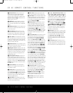
When using the full-OSD system to make the setup
adjustments, press the
OSD Button U
∫
once
so that the
MASTER MENU (Figure 1) appears.
The cursor will be next to the
IN/OUT SETUP
line
. Press the
Set
Button
p
œ
and the first page
of the
IN/OUT SETUP menu (Figure 2) will
appear on the screen. Press the
‹/› Naviga
tion
Button
D
©
until the desired input name appears
in the highlighted video,
as well as being indicated in
the front-panel
Input Indicators !.
Figure 2
When any input other than the tuner, 8-channel inputs
or the USB input, is selected as the source, you have
t
he option of renaming the input as it appears in the
on-screen and front-panel messages. This is helpful if
you wish to associate a specific product brand name
with the input, or to simply enter any name that will
help you to remember which source is being selected.
To change the input name, press the
⁄/¤ Navigation
Buttons
D
©
on the remote so that the cursor
i
s pointing to
T
ITLE
.
Next, press and hold the
Set Button p
œ
for a few seconds until a flashing
box appears to the right of the colon. Immediately
release the
Set Button p
œ
, as you are now
ready to enter the device name.
Press the
⁄/¤ Navigation Buttons D
©
and
note that alphanumeric characters will appear with
the start of the alphabet in capital letters, followed by
the lowercase letters, and then numbers and symbols.
When you press the
¤ Navigation Button D
©
, the symbols and numbers will appear first,
followed by a reverse list of the alphabet in lowercase
letters. Press the button either way until the first
letter of the desired name appears. If you wish to
enter a blank space as the first character, press the
› Navigation Button D
©
.
When the desired character appears, press the
›
Navigation Button D
©
and repeat the process
for the next letter, and continue until the desired name
is entered, up to a maximum of 14 characters. Press
the
Set Button p
œ
to enter the input name into
the system memory and to proceed with the configu-
ration process.
After entering the input title, press the
⁄/¤
Navigation Buttons D
©
to move to the
next line.
The audio input defaults are shown in the table in the
Appendix. If your system configuration follows the
default table
,
no changes are needed and you may
press the
⁄/¤ Navigation Buttons D
©
to
move to the next line.
With the cursor pointing to
AUDIO IN-PORT,
press the
‹/› Na
viga
tion Buttons
D
©
to
change the default to a different audio input connection.
When the name of the desired input appears, press
the
⁄/¤ Navigation Buttons D
©
to move
to the next line
.
In normal operation, when a digital audio stream is
interrupted,
the unit will automatically switch to the
analog inputs associated with that source. This is par-
ticularly useful with cable set-top boxes where the
input is normally digital, but occasionally changes to
analog. If you wish to configure an input so that the
auto-poll circuit is tur
ned off, while the on-screen cur-
sor is pointing to the
AUDIO
AUTO
POLL
line, simply press the ‹/› Navigation Buttons
D
©
so that OFF (rather than ON) is highlighted.
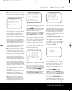
* IN/OUT SETUP *
SOURCE: VIDEO 1
TITLE:
AUDIO IN-PORT: ANALOG
AUDIO AUTO POLL: OFF ON
VIDEO IN PORT: AUTO
COMPONENT INPUT: COMP 1
VIDEO PROCESS: V CONVER
A/V SYNC DELAY: 0 mS
MASTER MENU PAGE 2
→→
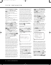
** MASTER MENU **
IN/OUT SETUP
AUDIO ADJUST
SURROUND SETUP
EZSET/EQ
MULTI-ROOM
ADVANCED
→→
SYSTEM CONFIGURATION
22 SYSTEM CONFIGURATION22 SYSTEM CONFIGURATION
AVR445 OM 6/23/06 3:13 PM Page 22