


18 INSTALLATION AND CONNECTIONS18 INSTALLATION AND CONNECTIONS
INSTALLATION AND CONNECTIONS
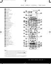
7. The default audio connection for a conventional
DVD player is to link the coaxial digital audio output
on the DVD player to the
Coaxial 1 Digital Audio
Input
a, but you may also make a connection to
either the
Coaxial a or Optical b digital inputs,
or to the
Analog DVD Audio Inputs Z. You
may change the assignment in the
IN/OUT
SETUP menu as described on page 22, or by
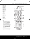
u
sing the front-panel
D
igital Input Selector
F.
8. To use a portable audio/video product such as a
camcorder, media player or digital still camera with
the AVR, or connect a video game console or other
source that may not always be connected to the
AVR, connect the video outputs of the source to the
Video 4 Input/Output Jacks N, behind the
Front-Panel Door 8. If the source has digital
audio outputs, connect them to the
Optical 4
Digital Input K or the Coaxial 4 Digital Input L.
CONNECTION NOTES:
• When making connections to the Component
Video Inputs
O or the Coaxial a or Optical
b digital audio inputs, it is a good idea to make
note of which jacks are connected to which
source, using the Worksheet in the Appendix. This
will help simplify the configuration process.
• When connecting a source device such as a
cable set-top box where the audio streams may
change between digital and analog as you
change channels, we recommend that you make
both analog and digital connections. The AVR’s
Auto Poll feature will automatically sense when
the digital stream is replaced by an analog output
and switch the input accordingly. (See page 22
for more information on the Auto-Poll feature.)
This dual connection is not required for sources
(such as DVD players or video games) that always
output a digital stream.
9. Connect the AVR to your video display using one of
the following connections, even if you will also use
an HDMI connection:
• If your video display has component video
inputs (Y/Pr/Pb), connect the
Component
Video/Monitor Outputs M.
• If your display does not have digital or compo-
nent video inputs, connect the Video Monitor
Output P on the AVR to the matching input on
your display. Only one connection is needed, and
S-video is the higher quality signal.
HDMI Connections
HDMI
™
is the abbreviation for High-Definition Multimedia
Interface, which is quickly becoming the standard for
connections between high-definition video/audio source
products and displays. HDMI is a digital connection, elimi-
nating the need to convert signals back and forth from
digital to analog.
Some source or display components in your system
may use DVI (Digital Video Interface) for digital video
connections. DVI carries the same digital video signals
as HDMI but uses a larger connector and does not
transport audio or control signals. In most cases, you
may mix and match DVI and HDMI digital video con-
nections by using optional connector adapters. Note,
however, that some DVI-equipped video displays are
not compatible with the HDCP copy protection coding
that is increasingly carried with signals connected
via HDMI. If you have an HDMI source and a DVI-
e
quipped display, you may occasionally be unable to
view a program if the display does not include HDCP.
This is not the fault of the AVR or your source; it sim-
ply indicates that the video display is not compatible.
The AVR 445 is equipped for HDMI switching, which
means that it is able to select either of the two HDMI
inputs as the source that feeds your system’s video
display. This preserves the digital signal in its original
form by passing it directly through from source to dis-
play. However, this also means that the AVR does not
have access to the signal and thus it is not able to add
menus or on-screen messages to HDMI signals, or to
process the audio that may be part of the signal in an
HDMI connection.
Therefore, the following connections are required when
the AVR 445 is used with HDMI sources:
• Connect the HDMI output of a source to either of
the
HDMI Inputs L.
• Connect the
HDMI Output K of the AVR to an
HDMI input on your display.
• Connect either an optical or coaxial digital audio
output from the source to the
A
VR. The default
connections are
Optical 3 b for a source con-
nected to
HDMI 1 L and Coaxial 3 a for a
source connected to
HDMI 2 L. You may use
any digital or analog audio source in conjunction
with the HDMI inputs, but if it varies from the
default you must make a change to the input’
s
setting, as shown on page 22.
•
Even when HDMI inputs are used, it is important to
make sure that a component, S-video or compos-
ite video connection is made between the AVR and
your display.
This is needed to view both the setup
menus and on-screen messages
, and to view other
(non-HDMI) video sources. The AVR 445 does not
convert analog video signals to HDMI.
System and Power Connections
The AVR 445 is designed for flexible use with multiroom
systems, external control components and power amplifiers.
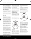
Main Room Remote Control Extension
If the receiver is placed behind a solid or smoked-
glass cabinet door, the obstruction may prevent the
remote sensor from receiving commands
.
In this
event, an optional remote sensor may be used.
Connect the output of the remote sensor to the
IR Input fl.
If other components are also prevented from receiving
remote commands, only one sensor is needed. Simply
use this unit’s sensor or a remote eye by running a
connection from the
IR Output ‹ to the Remote IR
Input jack on Harman Kardon or other compatible
e
quipment.
If other Harman Kardon-compatible source equipment
is part of the main room installation, the IR
Output
Jack
‹ on the rear panel should be connected
to the
I
R IN
j
ack on source equipment. This enables the remote
room location to control source equipment functions
.
When a remote IR sensor is used to control non-
Harman Kardon source equipment, we recommend
that you make a hard-wire connection or use an
optional, external IR “blaster” connected to the
Full
Carrier IR Output
B. If you are in doubt as to which
IR Output jack to use for the equipment in your sys-
tem, contact your dealer or installer, or the manufac-
turer’s support site and ask whether the unit to be
controlled uses “full carrier” IR commands. When “full
carrier” commands are used, make the connection to
the
Full Carrier IR Output ¤. Otherwise, make the
connection to the
IR Output ‹.
NOTE: All remotely controlled components must be
linked together in a “daisy chain.” Connect the
IR OUT
jack of one unit to the IR IN of the next to establish
this chain.
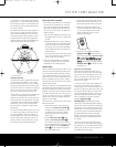
Multiroom Audio Connections
The AVR 445 is equipped with multizone capabilities
that allow it to send a separate audio source to the
remote zone from the one selected for use in the
main room.
Depending on your system’s requirements, three
options are available for audio connection:
Option 1: Use high-quality, shielded audio intercon-
nect cable from the AVR 445’s location to the remote
room. In the remote room, connect the interconnect
cable to a stereo power amplifier. The amplifier will be
connected to the room’s speakers. At the AVR 445,
plug the audio interconnect cables into the
Multiroom
Audio Outputs
8 on the
A
VR 445’
s rear panel.
Option 2: Connect the Multiroom Audio Outputs
8 on the AVR 445 to the inputs of an optional stereo
power amplifier. Run high-quality speaker wire from
the amplifier to the speakers in the remote room.
Option 3: Taking advantage of the AVR 445’s built-in
seven-channel amplifier, it is possible to use two of the
amplifier channels to power speakers in the remote
room.
When using this option, you will not be able to
use the full 7.1-channel capabilities of the AVR 445 in
the main listening room, but you will be able to add
another listening room without external power ampli-
fiers. To use the internal amplifiers to power a remote
INSTALLATION AND CONNECTIONS
AVR445 OM 6/23/06 3:13 PM Page 18