Installation Manual 59
Specifications
Output Wiring – Configurable I/O SpecificationsOutput Wiring – Fieldbus/PROFIBUSOutput Wiring – Intrinsically Safe Output Wiring – Configurable I/O SpecificationsOutput Wiring – Fieldbus/PROFIBUSOutput Wiring – Intrinsically Safe Output Wiring – Configurable I/O SpecificationsOutput Wiring – Fieldbus/PROFIBUSOutput Wiring – Intrinsically Safe Output Wiring – Configurable I/O SpecificationsOutput Wiring – Fieldbus/PROFIBUSOutput Wiring – Intrinsically Safe
• Discrete output (Model 2700 only):
- Can report event 1, event 2, event 1 or 2, flow direction, flow switch, calibration in
progress, or fault
- Configurable polarity: active high or active low
Model 2700 transmitters with non-intrinsically safe configurable input/outputs option board
(output option code B or C)
One or two 4–20 mA outputs:
• Channel A is always an mA output; Channel B is configurable as an mA output
• Not intrinsically safe
• Internally powered (active)
• Isolated to ±50 VDC from all other outputs and earth ground
• Maximum load limit:
- Channel A (mA1): 820 Ohms
- Channel B (mA2): 420 Ohms
• Can report mass flow, volume flow, density, temperature, or drive gain; transmitters with the
petroleum measurement application (API) or enhanced density application can also report
standard volume flow and density at reference temperature
• Linear with process from 3.8 to 20.5 mA, per NAMUR NE43 (June 1994)
0
1000
2000
3000
4000
5000
6000
7000
8000
9000
10000
5 7 9 11 13 15 17 19 21 23 25 27 29
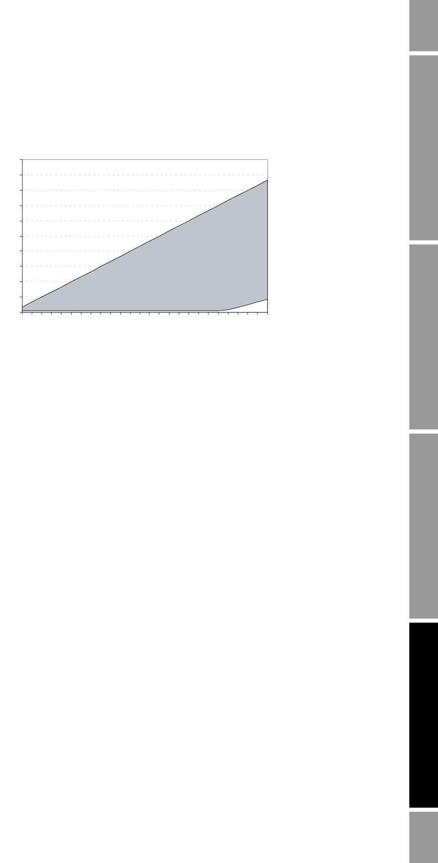
Frequency Output Load Resistance Value
R
max
= (V
supply
- 4)/0.003
*R
min
= (V
supply
- 25)/0.006
*Absolute minimum = 100 Ohms for V
supply
< 25.6 volts
Supply voltage (volts)
External resistor (Ohms)
Operating
Region


