42 Micro Motion
®
Model 1700 and 2700 Transmitters
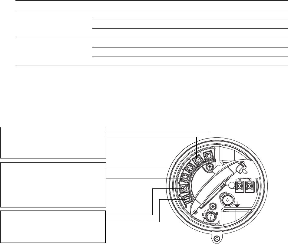
Output Wiring – Model 2700 Configurable I/O Transmitters
Figure 6-1 Configuration of configurable I/O terminals
6.3 mA output wiring
The following 4–20 mA wiring diagrams are examples of proper basic wiring for the Model 2700
primary and secondary mA outputs. The following options are shown:
• Basic mA wiring (Figure 6-2)
• HART/analog single-loop wiring (Figure 6-3)
• HART multidrop wiring (Figure 6-4)
Note: If you will configure the transmitter to poll an external temperature or pressure device, you
must wire the mA output to support HART communications. You may use either HART/analog
single-loop wiring or HART multidrop wiring.
Table 6-1 Channel configuration
Channel Terminals Configuration options Power
A 1 & 2 mA output with HART/Bell 202
(1)
(1) The Bell 202 signal is superimposed on the mA output.
Internal
B 3 & 4 • mA output (default) Internal
• Frequency output Internal or external
(2)
(2) You must provide power to the outputs when a channel is set to external power.
• Discrete output Internal or external
C 5 & 6 • Frequency output (default)
(3)
(3) When configured for two frequency outputs (dual pulse), frequency output 2 is generated from the same signal that is sent
to the first frequency output. Frequency output 2 is electrically isolated but not independent.
Internal or external
• Discrete output Internal or external
• Discrete input Internal or external
Terminals 1 and 2 (Channel A)
mA1 output
Internal power only
HART (Bell 202) communications
Terminals 3 and 4 (Channel B)
mA2 output or FO or DO1
Power:
• mA – internal only
• FO or DO – internal or external
No communications
Terminals 5 and 6 (Channel C)
FO or DO2 or DI
Power: internal or external
No communications
mA = milliamp
FO = frequency output
DO = discrete output
DI = discrete input
+
–
+
–
+
–


