


Installation Manual 55
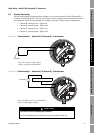
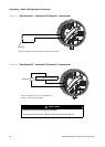
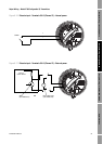
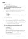
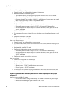
Output Wiring – Configurable I/O SpecificationsOutput Wiring – Fieldbus/PROFIBUSOutput Wiring – Intrinsically Safe
Appendix A
Specifications
A.1 Functional specifications
The Model 1700 or 2700 transmitter’s functional specifications include:
• Electrical connections
• Input/output signals
• Digital communication
•Power supply
• Environmental requirements
• Ambient temperature effect
• EMC compliance
A.1.1 Electrical connections
Output connections
The transmitter has two (Model 1700) or three (Model 2700) pairs of wiring terminals for
transmitter outputs.
• The Model 1700/2700 with analog outputs option board has one pair of wiring terminals for
digital communications (Modbus or HART protocol on RS-485)
• On the Model 2700 with F
OUNDATION fieldbus or PROFIBUS-PA, terminals 3–6 are not used.
Screw terminals accept one or two solid conductors, 14 to 12 AWG (2,5 to 4,0 mm
2
), or one or two
stranded conductors, 22 to 14 AWG (0,34 to 2,5 mm
2
).
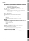
Power connection
The transmitter has two pairs of wiring terminals for the power connection:
• One pair of wiring terminals accepts AC or DC power
• One internal ground lug for power-supply ground wiring
Screw terminals accept one or two solid conductors, 14 to 12 AWG (2,5 to 4,0 mm
2
), or one or two
stranded conductors, 22 to 14 AWG (0,34 to 2,5 mm
2
).
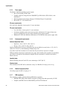
Service port connection
The transmitter has two clips for temporary connection to the service port.