34 Micro Motion
®
Model 1700 and 2700 Transmitters
Output Wiring – Model 1700/2700 Intrinsically Safe Transmitters
5.3 Safe area output wiring
The following notes and diagrams are designed to be used as a guide for wiring the Model 1700 or
Model 2700 outputs for safe area applications.
5.3.1 Safe area mA output wiring
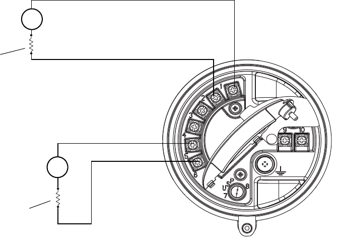
The following 4–20 mA wiring diagrams are examples of proper basic wiring for the Model 1700 mA
output or Model 2700 primary and secondary mA outputs.
Note: This diagram shows the Model 2700, which has a secondary mA output. If you are using the
Model 1700, the secondary mA output does not exist.
Figure 5-1 Safe area basic mA output wiring
Note: See Figure 5-2 for voltage and resistance values.
VDC
VDC
R
load
R
load
+
–
+
–
+
–
+
–
mA1
mA2


