


Installation Manual 23
Wiring the Transmitter to the Sensor
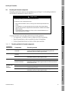
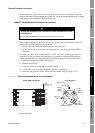
Installing the Transmitter Output Wiring – AnalogSensor WiringBefore You Begin
If using jacketed cable:
a. Ground the shield drain wires (the black wire) only on the core processor end, by
connecting it to the ground screw inside the lower conduit ring. Never ground to the core
processor’s mounting screw. Never ground the shield drain wires at the sensor junction
box.
If using shielded or armored cable:
a. Ground the shield drain wires (the black wire) only on the core processor end, by
connecting it to the ground screw inside the lower conduit ring. Never ground to the core
processor’s mounting screw. Never ground the shield drain wires at the sensor junction
box.
b. Ground the cable braid on both ends, by terminating it inside the cable glands.
4. Ensure integrity of gaskets, grease all O-rings, then close the junction box housing and core
processor end-cap, and tighten all screws.
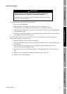
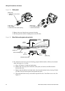
3.5 Wiring for remote core processor with remote transmitter installations
This task includes two subtasks:
• Subtask 1: Wiring the remote core processor to the transmitter (4-wire cable)
• Subtask 2: Wiring the sensor to the remote core processor (9-wire cable)
Subtask 1: Wire the remote core processor to the transmitter
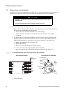
1. Use one of the following methods to shield the wiring from the core processor to the
transmitter:
• If you are installing unshielded wiring in continuous metallic conduit that provides
360° termination shielding for the enclosed wiring, go to Subtask 1, Step 6.
• If you are installing a user-supplied cable gland with shielded cable or armored cable,
terminate the shields in the cable gland. Terminate both the armored braid and the shield
drain wires in the cable gland. Go to Subtask 1, Step 6.
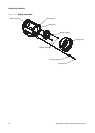
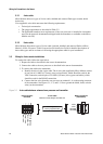
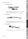
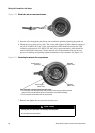
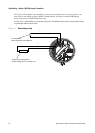
• If you are installing a Micro Motion-supplied cable gland at the core processor housing:
- Refer to Figure 3-5 to identify the cable gland to use for the 4-wire cable conduit
opening.
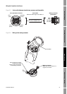
- Prepare the cable and apply shielded heat shrink to the cable (see Figure 3-6). The
shielded heat shrink provides a shield termination suitable for use in the gland when
using cable whose shield consists of foil and not a braid. Proceed to Subtask 1, Step 2.
- With armored cable, where the shield consists of braid, prepare the cable as described
below, but do not apply heat shrink. Proceed to Subtask 1, Step 2.
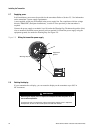
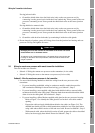
CAUTION
Damaging the wires that connect the transmitter to the sensor can cause
measurement error or flowmeter failure.
To reduce the risk of measurement error or flowmeter failure, when closing the
housings on the sensor and core processor, make sure that the wires are not
caught or pinched.