


26 Micro Motion
®
Model 1700 and 2700 Transmitters
Wiring the Transmitter to the Sensor
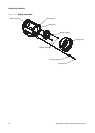
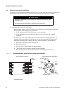
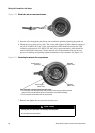
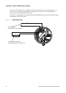
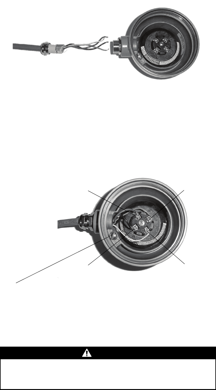
Figure 3-10 Gland body and core processor housing
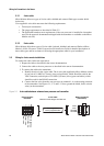
5. Insert the wires through the gland body and assemble the gland by tightening the gland nut.
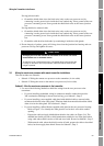
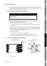
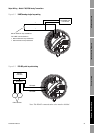
6. Identify the wires in the 4-wire cable. The 4-wire cable supplied by Micro Motion consists of
one pair of 18 AWG (0,75 mm
2
) wires (red and black), which should be used for the VDC
connection, and one pair of 22 AWG (0,35 mm
2
) wires (green and white), which should be
used for the RS-485 connection. Connect the four wires to the numbered slots on the core
processor, matching corresponding numbered terminals on the transmitter. See Figure 3-11.
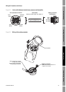
Figure 3-11 Connecting the wires at the core processor
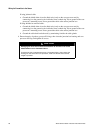
7. Reinstall and tighten the core processor housing cover.
CAUTION
Twisting the core processor will damage the equipment.
Do not twist the core processor.
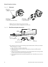
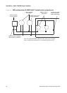
Power supply +
(Red wire)
Power supply –
(Black wire)
RS-485A
(White wire)
RS-485B
(Green wire)
Core processor housing internal ground screw
• For connections to earth ground (if core processor cannot be grounded via sensor
piping and local codes require ground connections to be made internally)
• Do not connect shield drain wires to this terminal