


Installation Manual 41
Output Wiring – Configurable I/O SpecificationsOutput Wiring – Fieldbus/PROFIBUSOutput Wiring – Intrinsically Safe
Chapter 6
Output Wiring – Model 2700 Configurable I/O
Transmitters
6.1 Overview
This chapter explains how to wire outputs for Model 2700 transmitters with the configurable
input/outputs board (output option code B or C).
Note: If you don’t know what outputs option board is in your transmitter, see Section 1.4.
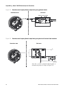
Output wiring requirements depend on how you will configure the transmitter terminals. The
configuration options are shown in Table 6-1 and Figure 6-1.
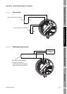
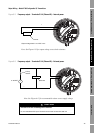
If Channel B is configured as a frequency output or discrete output, it can also be configured to use
either internal or external power. Channel C can be configured to use either internal or external power,
independent of its output configuration.
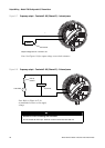
• “Internal power” means that the terminals are powered automatically by the transmitter. The
output wiring instructions do not include power setup and power wiring.
• “External power” means that the terminals must be connected to an independent power supply.
The output wiring instructions include power setup and power wiring.
Note: The terms “active” and “passive” are sometimes used to describe internally and externally
powered outputs.
It is the user’s responsibility to verify that the specific installation meets the local and national safety
requirements and electrical codes.
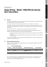
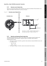
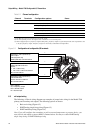
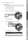
6.2 Channel configuration
The six terminals are divided into three pairs, and called Channels A, B, and C. Channel A is
terminals 1 and 2; Channel B is terminals 3 and 4; and Channel C is terminals 5 and 6. Variable
assignments are governed by channel configuration. Table 6-1 and Figure 6-1 show how each channel
may be configured, and the power options for each channel.
You can use a HART Communicator or ProLink II software to configure channels. To configure
channels, see the manual entitled Series 1000 and 2000 Transmitters Configuration and Use Manual.
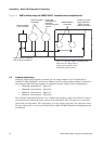
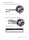
Note: You cannot configure the following combination: Channel B = discrete output, Channel
C = frequency output. If you need both a frequency output and a discrete output, use the following:
Channel B = frequency output, Channel C = discrete output. For more information, see the manual
entitled Series 1000 and 2000 Transmitters Configuration and Use Manual.