300 Agilent N5161A/62A/81A/82A/83A MXG Signal Generators User’s Guide
Working in a Secure Environment
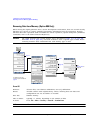
Understanding Memory Types
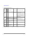
Firmware
Memory
(Flash)
8 MB
No Yes main firmware image factory installed or
firmware upgrade
CPU board (same chip as main flash memory,
but managed separately)
During normal operation, this memory cannot
be overwritten. It is only overwritten during
the firmware installation or upgrade process.
Because this memory chip contains 8 MB of
user data and 8 MB of firmware memory
(described here), a full–chip erase is not
desirable. User data areas are selectively and
completely sanitized when you perform the
Erase and Sanitize function.
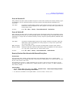
Bootrom
Memory
(EEPROM)
8 kB
No Yes CPU bootup parameters
no user data
factory programmed CPU board
During normal operation, this memory cannot
be overwritten or erased except for LAN
configuration. This read–only data is
programmed at the factory.
Yes Yes LAN configuration Front panel entry or
remotely
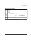
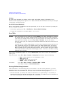
Calibration
Data
(Flash)
256 kB
No Yes factory
calibration/configuration data
backup
no user data
factory or service
only
RF Board
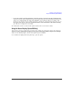
LCD
Display
Memory
(RAM)
160 kB
No No display buffer operating system RF board, not battery backed.
Front Panel
Memory
(Flash)
32 kB
No No front panel keyboard
controller firmware
no user data
operating system Front Panel board
a
Analog instruments only
Table 13-1 Base Instrument Memory (Continued)
Memory
Type and
Size
Writable During
Normal Operation?
Data Retained
When Powered Off?
Purpose/Contents Data Input Method Location in Instrument and Remarks


