Agilent N5161A/62A/81A/82A/83A MXG Signal Generators User’s Guide 93
Preliminary Optimizing Performance
Preliminary Using Flatness Correction
Configure the U2000A/01A/02A/04A Power Sensor
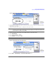
1. Connect the power sensor to the signal generator’s front panel USB port. Refer to “Connect the
Equipment” on page 91.
2. Zero the power sensor using the signal generator softkeys.
CAUTION Verify the signal generator RF Output power is set to the desired amplitude before
performing the power meter zero. No RF Output amplitude check is done by the signal
generator during zero.
NOTE The signal generator’s RF Output LED remains unchanged during zeroing of the power
sensor (e.g. if the RF Output LED was on prior to starting the Zeroing of the power sensor,
the LED remains on throughout the zero/calibration). But, actually the instrument’s firmware
has turned off the RF Output’s power.
For operating information on your particular power sensor, refer to its operation guide.
Configure the E4419A/B and N1911A/12A Power Meter
1. Select SCPI as the remote language for the power meter.
2. Zero and calibrate the power sensor to the power meter, using the softkeys on the signal
generator or the front panel of the power meter.
3. Enter the power sensor calibration factors into the power meter as required.
4. Enable the power meter’s cal factor array.
NOTE The signal generator’s RF Output LED remains unchanged during zeroing of the power
sensor (e.g. if the RF Output LED was on prior to starting the Zeroing of the power sensor,
the LED remains on throughout the zero/calibration). But, actually the instrument’s firmware
has turned off the RF Output’s power.
For operating information on your particular power meter/sensor, refer to its operating
guide.
Example: A 500 MHz to 1 GHz Flatness Correction Array with 10 Correction Values
Create the User Flatness Array
1. Configure the signal generator:
a. Preset the signal generator.
b. Set the signal generator’s connection type to the power meter/sensor:
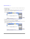
i. Press AMPTD > More > User Flatness > Configure Power Meter > Connection Type > connection
type.
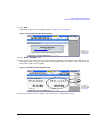
ii. If connection type is USB:
1. Zero Sensor
2. Go to step c.


