100 Agilent N5161A/62A/81A/82A/83A MXG Signal Generators User’s Guide
Optimizing Performance Preliminary
Using External Leveling (N5183A Only)Preliminary
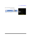
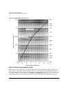
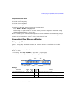
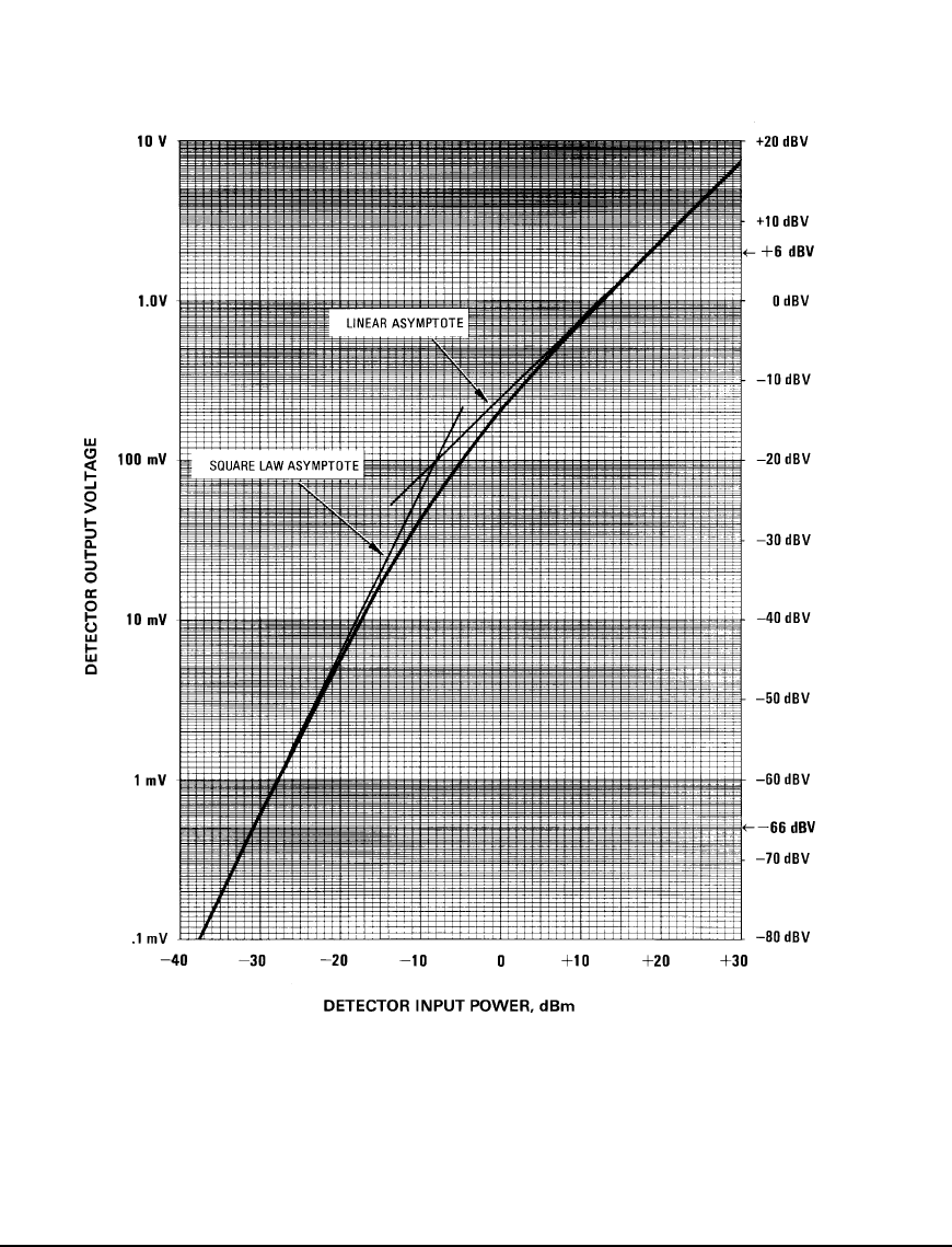
Figure 5-18 Typical Diode Detector Response at 25° C
Option 1E1 Output Attenuator Behavior and Use
When using the internal detector, the Option 1E1 output attenuator enables signal generator power
levels down to −135 dBm at the RF Output connector. It accomplishes this by adding attenuation to
the output signal after the ALC detection circuit. The output power value (shown in the Amplitude
area of the display) is the resultant of the Set Atten and Set ALC Level values (see page 97). With the
external detector selected, the output attenuator no longer attenuates the output signal since the


