Chapter 1 15
Introduction
System displays
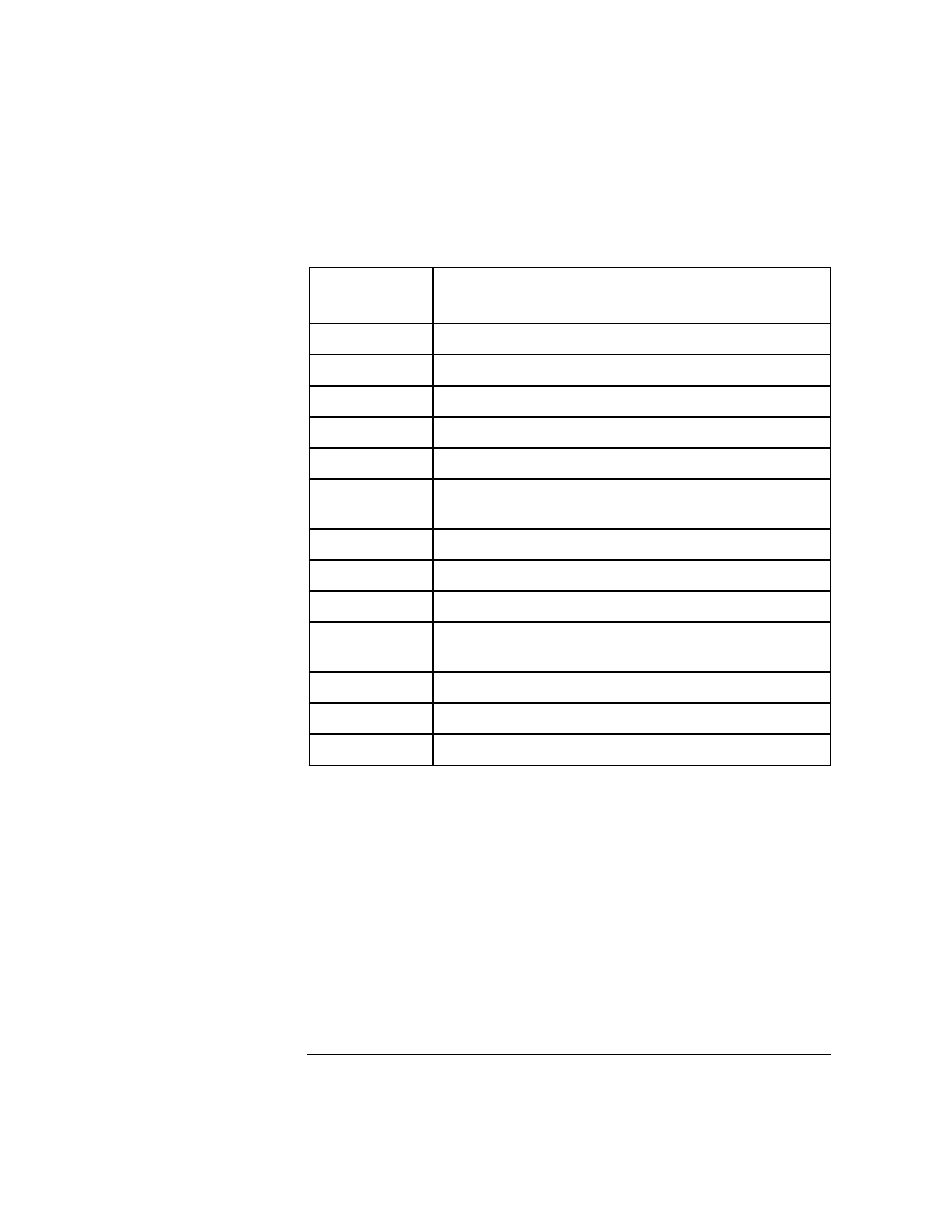
Table 4 Message display line
Power supply indicators
When the keyswitch on the operator panel is in the DC ON position both
the AC power (amber) LED and the DC power (green) LED on each of the
power supplies should be on.
Message
display code
Description
a Utilities board (SCUB) hardware initialization.
b Processor initialization/selftest rendezvous.
c Utilities board (SCUB) SRAM test. (optional)
d Utilities board (SCUB) SRAM initialization.
e Reading Node ID and serial number.
f Verifying non-volatile RAM (NVRAM) data
structures.
g Probing system hardware (ASICs).
h Initializing system hardware (ASICs).
i Probing processors.
j Initialing, and optionally testing, remaining SCUB
SRAM.
k Probing main memory.
l Initializing main memory.
r Enabling system error hardware.


