


14 ENGLISH
4. Installation
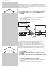
4.1 General remarks
– Most input sockets of your DFR9000 are assigned for connection to a specific device.
In the next chapters we will therefore only describe how to connect these specific devices
to your DFR9000. If you wish to connect other devices, you first reassign the sockets for
connection to these devices.This can be done in the system menu.
For this see '6.7 Reassigning input sockets' and '10.7 A/V Input menu'.
Connections can then be made as described below. Please refer to the chapter
'Functional overview' for an overview of connectors and the devices they are assigned to.
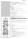
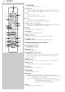
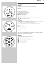
– The numbers between brackets refer to the numbers in the illustrations on page 3.
– The arrows in the illustrations indicate the direction of the signal.
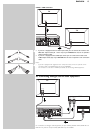
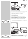
4.2 Connecting to your TV
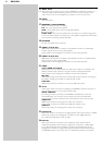
SCART/RGBS connection
• Make sure the receiver is switched off and unplugged from the wall outlet before making
any connections.
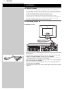
• Connect the Scart control (2.5 mm jack) of the 6-cinch + Scart control to Scart cable
supplied to the SCART CONTROL connector (22) of your DFR9000.
> When your DFR9000 is reactivated after being switched off, Scart control switches your
Scart-enabled TV to the correct input source immediately.
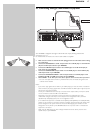
• Connect the red, green, blue and yellow plugs of the cable to the corresponding VIDEO
OUT connectors (22) of your DFR9000.
• Connect the red and white audio plugs of the cable to the corresponding LINE OUT
connectors (22) of your DFR9000.
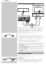
• Connect the Scart connector at the other end of the cable to the Scart input connector
of your TV.
CD IN CD-R IN AUX IN
SCART INPUT
TV