


10 ENGLISH
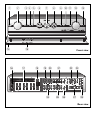
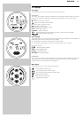
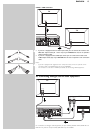
3.2 Rear view
Note: Most of the input connectors at the rear of your DFR9000 are assigned for connecting to a
specific audio/video playback/recording device.These connectors can be reassigned in the
system menu. For this see ‘6.7 Reassigning input sockets’ and ‘10.7 A/V input menu’.
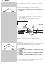
16 MAINS
Mains inlet socket.
17 SPEAKERS (4 OHM NOMINAL)
Speaker connection panel for connecting:
L/R - Left (L) and right (R) front speakers;
SL/SR - Surround left (SL) and surround right (SR) speakers;
C - Centre speaker.
6.1SB/5.1SUB - Surround back speaker.To be connected in a 6.1 speaker configuration.
If no surround back speaker is connected (5.1 or less speaker configuration), these sockets
can be used for connecting a passive subwoofer.
18 ANTENNA
FM-, AM- and DAB antenna connectors.
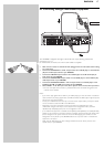
19 VIDEO 1 IN (R, G, B, S)
RGBS video input sockets for connection to the SCART connector of a DVD player/
recorder using the 6-cinch to Scart cable supplied.
These sockets can be reassigned for connection to other video equipment.
20 VIDEO 2 IN (R, G, B, S)
RGBS video input sockets for connection to the SCART connector of a satellite receiver,
using the 6-cinch to Scart cable supplied.
These sockets can be reassigned for connection to other video equipment.
21 VIDEO
TV IN / GAME IN / DVD IN
CVBS (upper row) and S-Video (lower row) video input sockets for connecting to the
CVBS or S-Video output sockets of a TV, game console or DVD player/recorder.
These sockets can be reassigned for connection to other video equipment.
REC OUT
CVBS (upper socket) and S-Video (lower socket) video output sockets for connecting to
the CVBS or S-Video input sockets of a DVD recorder or VCR.
CVBS OUT
CVBS output socket for connection to a TV with a CVBS input socket.
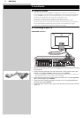
22 TO TV
These output sockets are used for connecting your DFR9000 to the Scart connector of
your TV, using the 6-cinch + Scart control to Scart cable.
SCART CONTROL
For inserting the 2.5mm jack.When your DFR9000 is activated, Scart control will
automatically switch your TV to the correct (active) input source (provided that a
Scart connection has been made).The active source will be shown on the TV screen.
VIDEO OUT
RGBS output sockets for inserting the four video cinch connectors.
These sockets can also be connected to the RGB input sockets of a TV.
LINE OUT
Audio output sockets for inserting the two audio cinch connectors.
23 OPTICAL IN
Audio input socket for connection to the digital (optical) audio output socket of a satellite
receiver.This socket can be reassigned for connection to other digital equipment
(e.g. a CD player, DVD player or CD recorder).
24 M-CH IN
Audio input sockets for connection to the multichannel audio output sockets of
multichannel equipment.These sockets are assigned for connection to a SACD player.
If no multichannel equipment is available the L/R, SL/SR and C/SUB sockets can be
reassigned for connection to analog audio equipment (CD IN, CD-R IN and AUX IN).
The SBL/SBR sockets has no function when no multichannel equipment is connected.