16
Y
P
B
P
R
COMPONENT VIDEO
L
R
R
L
R
L
R
L
ININ
IN
IN
OUT OUT
VIDEO
1
VIDEO
2
PRE OUT
COAXIAL
OPTICAL
OPTICAL
IN
OUT
OUT
MONI
OUT
VIDEO
2
VIDEO
1
ININ
OUT
SUB
WOOFER
FRONT
SPEAKERS
A
B
SURROUND
SPEAKERS
CENTER
SPEAKER
VIDEO
S VIDEO
R
L
R
L
R
L
FRONT
SPEAKERS
A
B
SURROUND
SPEAKERS
CENTER
SPEAKER
R
L
R
L
R
L
FRONT
SPEAKERS
A
B
SURROUND
SPEAKERS
CENTER
SPEAKER
DIGITAL
OUT
DIGITAL IN
VIDEO 1
VIDEO 2
TAPE/CD-R
TV/LINE
AUDIO
ANTENNAANTENNA
+–+–
+–
+–
+–
+– +–
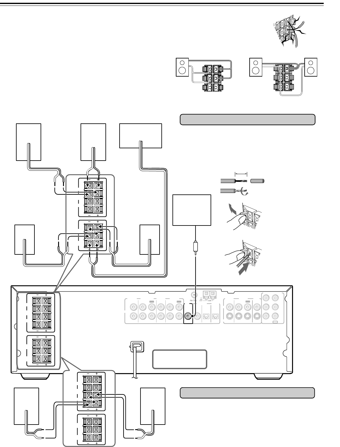
Connecting Speakers
Before connecting
• Refer also to the instruction manuals of the speakers.
• This DVD Changer Receiver is designed to reproduce optimum
sound quality when speakers with the impedances specified
below are connected. Please check the following information and
choose speakers with appropriate impedances for the
connections.
Front speakers: 6 ohms min. per speaker
Center speaker: 6 ohms min.
Surround Speakers : 6 ohms min. per speaker
• To prevent damage to circuits, never short-
circuit the positive (+) and negative (–)
speaker wires.
• Do not connect the speaker cable to the L
and R connectors at the same time and do
not connect more than one speaker to the
same speaker connectors.
Surround
(R)
10 mm (3/8”)
Active
subwoofer
Surround
(L)
Connecting to SPEAKERS A
The main speaker system is SPEAKERS A. Follow the
illustration on the left.
How to connect to the speaker
connectors
Press and hold
the lever.
Insert the stripped
end of the cord.
By releasing the
lever, the lever is
replaced.
Front (R) Front (L)
Connecting to SPEAKERS B
To place the additional speaker system (for the second
room), make the SPEAKERS B connection on the left.
NO!
DO NOT connect the
power cord (mains lead)
at this time.
NO!
NO!
–
–
+
+
R
L
–
–
+
+
R
L
Front (R) Front (L) Center
Strip 10 mm (3/8”)
from the end of
each cord, then
twist the exposed
wires tightly.


