


9
KRF-V7771D (En/T)
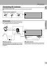
System connections
Connections
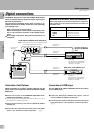
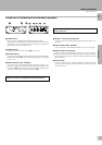
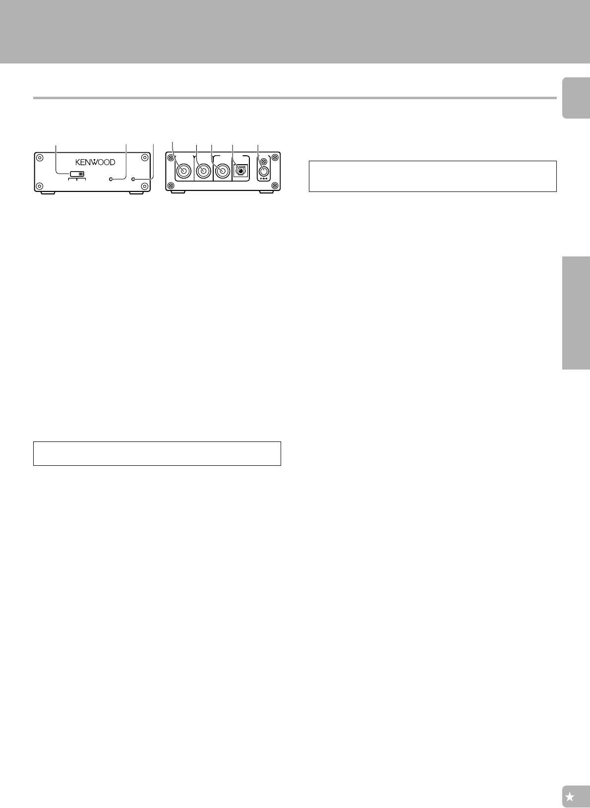
LASER DISC RF DEMODULATOR DEM-9991D (Optional)
Place the power supply away from the demodulator, receiver,
and any antennas.
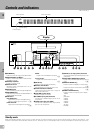
1 POWER switch
Use to switch the POWER OFF/ POWER ON (OPT./ COAX.).
Regardless of the OPT./COAX. switch setting, the input is switched
automatically to the Dolby Digital (AC-3) RF input whenever the
Dolby Digital (AC-3) RF signal is input.
2 POWER indicator
Lights (red) when the power switch (1) is set to ON.
3 RF LOCK indicator
Lights when a Dolby Digital (AC-3) RF signal is input to the RF INPUT
(AC-3 RF INPUT) jack (5). (This indicator is extinguished when a digital
input is in use.)
4 DIGITAL OUTPUT COAX. (COAXIAL)
Connect this jack to the VIDEO4 COAXIAL (DIGITAL IN) jack on your
Reciever. It outputs Dolby Digital (AC-3) coaxial digital signals when
the POWER (1) is set to COAX. and a Dolby Digital (AC-3) RF signal
is input to the RF INPUT (AC-3 RF INPUT) jack (5).
5 RF INPUT AC-3 RF (Dolby Digital RF)
Connect this jack to the Dolby Digital (AC-3) RF OUTPUT jack on your
LD player.
6 DIGITAL INPUT COAX. (COAXIAL)
Connect this jack to the COAXIAL OUTPUT jack on your LD player.
7 DIGITAL INPUT OPT. (OPTICAL)
Connect this jack to the OPTICAL OUTPUT jack on your LD player.
÷ When there are simultaneous inputs through the RF INPUT (AC-3 RF)
jack and DIGITAL INPUT jack, the input through RF INPUT (AC-3 RF) is
given the priority.
8 DC IN 12V jack
Connect this jack to the AC adaptor supplied with your demodulator.
Connect the AC adaptor to a wall outlet after completing all of the
other connections.
POWER
RF
LOCK
LASER DISC RF DEMODULATOR DEM-9991D
3
2
1
OFF OPT. COAX.
EXTERNAL DC SUPPLY DC 12V
8
DIGITAL OUTPUT
COAX.
DIGITAL INPUTRF INPUT
COAX.
DC IN
OPT.
AC-3 RF
56
7
4
“Dolby” and “AC-3” are trademarks of Dolby Laboratories.