


8
KRF-V7771D (En/T)
System connections
Connections
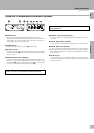
COAX.
COAX.
POWER
RF
LOCK
LASER DISC RF DEMODULATOR DEM-9991D
DIGITAL IN
VIDEO 2
COAXIAL
VIDEO 3
COAXIAL
VIDEO 4
OPTICAL
CD 1
OPTICAL
SL 16
TEXT
NITOR
OUT
DEO 3
VIDEO 4
OFF OPT. COAX.
OPT.
AC-3 RF
DC IN
DIGITAL OUTPUT
DIGITAL INPUTRF INPUT
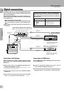
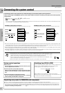
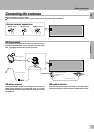
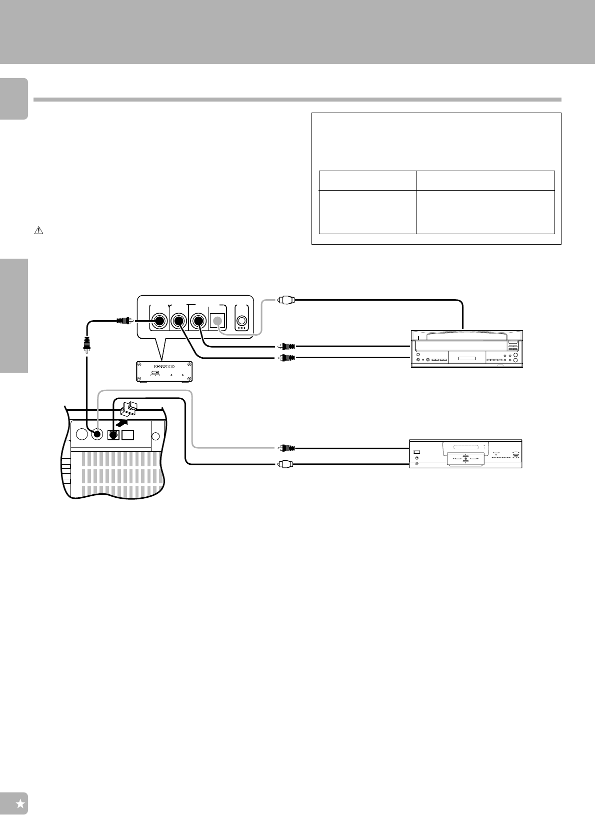
Digital connections
DIGITAL OUT
(COAXIAL)
DVD player with DIGITAL OUT
LASER DISC RF DEMODULATOR (DEM-9991D)
Note : Only required if you wish to play Laser Discs
in the Dolby Digital (AC-3) format
DIGITAL OUT
(OPTICAL)
DIGITAL OUT
(COAXIAL)
DIGITAL OUT
(OPTICAL)
AC-3 RF OUT
(COAXIAL)
DIGITAL OUT
(COAXIAL)
Note : Connect either optical or co-
axial cord.
Should not be connected both.
Connection of coaxial cord is
used as an example.
The DIGITAL IN jacks can accept either MPEG, Dolby Digital
(AC-3) or PCM (CD Format) signals (the input signal type is
detected automatically).
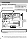
The connected components shown here are given as ex-
amples because the available models may vary depending
on marketing areas.
Make connections as shown below.
When connecting the related system components, refer
also to the instruction manuals of the related compo-
nents.
Do not plug in the power lead until all connections are
completed.
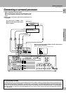
LD player with AC-3
RF OUT and DIGITAL
OUT
Connection of an LD player
When connecting an LD player with AC-3 RF OUT, the LD
player needs to be connected to the RF demodulator (DEM-
9991D) first.
1 Connect the LD player to the KENWOOD LASER DISC RF DE-
MODULATOR (DEM-9991D : optional).
÷ If your LD player can be connected to the receiver directly, connect it
to the DIGITAL IN, VIDEO 3 COAXIAL.
2 Connect the demodulator to the receiver’s DIGITAL IN, VIDEO 3
COAXIAL jack.
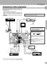
3 Connect the video signal and analog audio signals to the VIDEO
3 jacks. ( See “Connection of video components”.
7)
Connection of a DVD player
Use the DIGITAL IN, VIDEO 4 OPTICAL jack for the connec-
tion of a DVD player.
1 Connect the DVD player’s DIGITAL OUT (optical) with the
receiver’s DIGITAL IN, VIDEO 4 OPTICAL jack.
2 Connect the video signal, S Video signal and analog audio signals
to the VIDEO 4 jacks. ( See “Connection of video components”.
7)
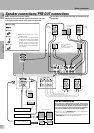
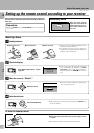
When using digital inputs, perform connection and assignment
taking special care in the relations between the input jacks and
connection cords.
COAXIAL connector
COAXIAL connector
OPTICAL connector
OPTICAL connector
Usable cord connectorDIGITAL INPUT jack
VIDEO2
VIDEO3
VIDEO4
CD1
Notes on DIGITAL INPUT jacks and connectors
Note : Connect either optical or co-
axial cord.
Should not be connected both.
Connection of optical cord is
used as an example.