


6
KRF-V7771D (En/T)
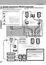
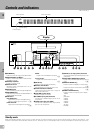
System connections
Connections
SYSTEM
CONTROL
FRONT SPEAKERS
(4-16 Ω)
CENTER
SPEAKER
(4-16 Ω)
SURROUND SPEAKERS
DIGITAL IN
VIDEO 2
COAXIAL
VIDEO 3
COAXIAL
VIDEO 4
OPTICAL
CD 1
OPTICAL
SL 16 XS 8
(
SL 16
)
(
XS 8
)
(
4-16 Ω
)
SWITCHED TOTAL
90W MAX.
L
R
A
L
R
L
C
R
B
SL 16
TEXT
L
R
R
ANTENNA
AM
-
FM 75Ω
GND
CD1
PHONO
MD/
TAPE 1
REC
OUT
PLAY
IN
REC
OUT
PLAY
IN
PLAY
IN
PLAY
IN
CD2 /
TAPE 2
MONITOR
MONITOR
OUT
FRONT
FRONT
SURROUND
SURROUND
CENTER
CENTER
SUB
WOOFER
SUBWOOFER
L
L
R
L
R
VIDEO
S VIDEO
PRE OUT
VIDEO4 6CH. INPUT
AUDIO
VIDEO 3
VIDEO 4
PLAY
IN
VIDEO 2
VIDEO 1
L
R
AUDIO
PLAY
IN
REC
OUT
+
-
6CH
2CH
VIDEO 4
INPUT
*
2
*
1
Caution regarding placement
To maintain proper ventilation, be sure to leave a space around the unit (from the largest outer dimensions including projections) equal to , or greater
than; Left and right panels : 10 cm, Rear panel : 10 cm, Top panel : 50 cm
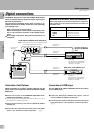
*2Note on the SL-16 TEXT jack (provided except for some destination areas): When using a KENWOOD CD player equipped with the SL-
16 TEXT jack, connect it to this unit using the communication cord provided with the CD player. This makes it possible to display the
disc and track titles on the remote control unit (provided with this unit).
Do not forget to set the SL-16 / XS-8 switches of the CD player and this unit to SL-16.
1.Connect all cords firmly. Loose connections may prevent proper sound transmission or produce noise.
2.Be sure to remove the power cord from the AC outlet before plugging or unplugging any connection cords. Plugging / unplugging connection
cords without disconnecting the power cord can cause malfunctions and may damage the unit.
3.Do not connect power cords from components whose power consumption is larger than what is indicated on the AC outlet at the rear of
this unit.
Ventilation fan
The ventilation fan runs during high-power reproduction. To allow for proper ventilation, maintain a certain distance (more than about 10 cm ,4 inches)
between the wall and the rear of the component.
U.K.
To wall AC
outlet
CAUTION (For U.K.)
When using the AC
outlets equipped with
this unit, be sure to
consult your dealer for
the corresponding
plug.
CD
OPTICAL
DIGITAL
OUT
REC IN
PLAY OUT
OUTPUT B : CD2
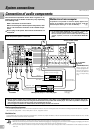
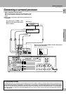
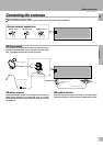
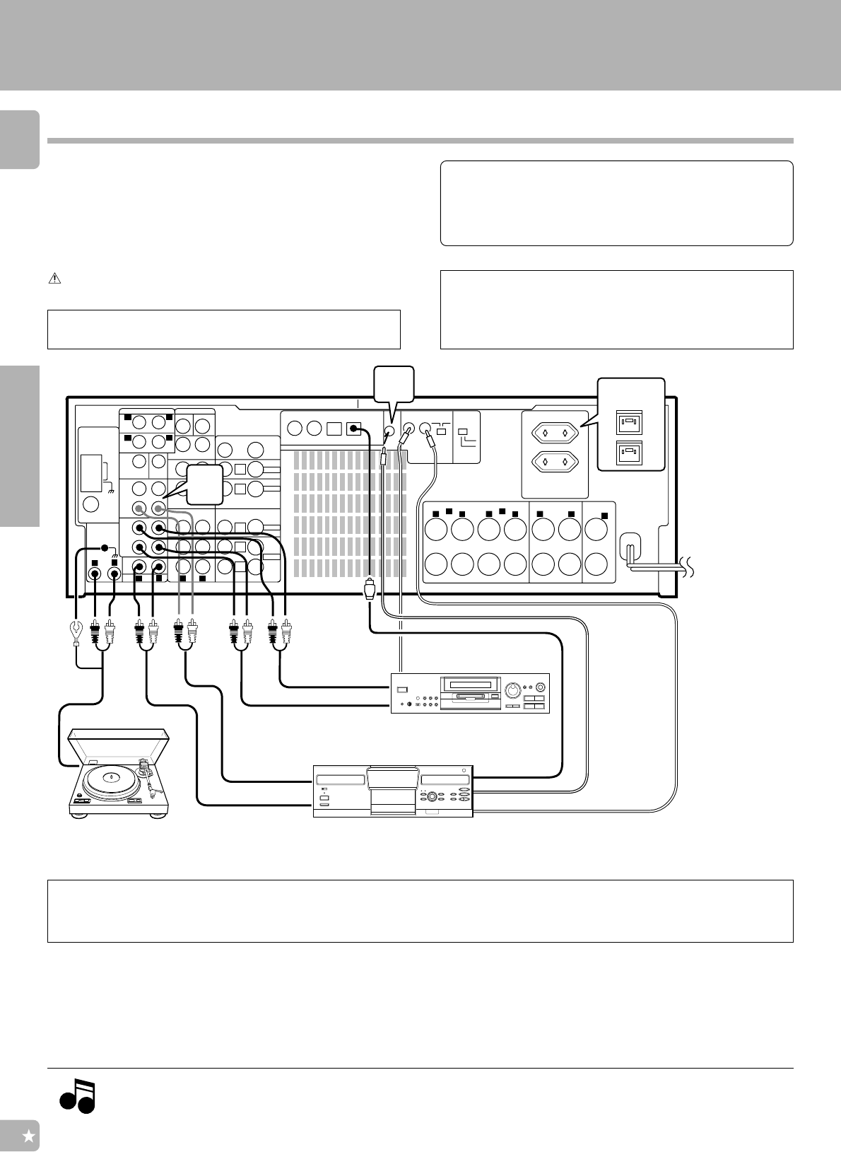
System connections
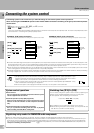
Connection of audio components
Malfunction of microcomputer
If operation is not possible or erroneous display appears even
though all connections have been made properly, reset the
microcomputer referring to “In case of difficulty”.
W
Shape of AC outlet
System control cord0
System control
cord
0
Communication
cord (SL16-TEXT)
MD recorder or cassette deck
Turntable
Multiple CD player or other CD player
The connected components shown here are given as ex-
amples because the available models may vary depending
on marketing areas.
Make connections as shown below.
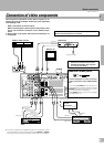
When connecting the related system components, refer
also to the instruction manuals of the related compo-
nents.
Do not plug in the power lead until all connections are
completed.
Also connect the system control cords when the KENWOOD
Audio Component System is connected.
*1To the CD2/TAPE2 MONITOR jacks, connect a second CD
player, a second cassette deck or a graphic equalizer.
Do not connect system control cord to the unit (except for
graphic equalizer) connected to the CD2/TAPE2 MONITOR
jacks.
OUTPUT A : CD1
Notes
Notes