


9
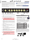
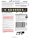
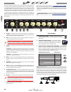
M. EXTERNAL SPEAKER OUTPUT (200/500 COMBO
ONLY) — Connect an 8Ω (minimum impedance)
speaker cabinet here. The power rating of the external
cabinet should meet or exceed the rating listed on the
amplier.
N. HORN SWITCH (200/500 COMBO ONLY) — Press to the
"ON" position to turn the horn on. Press to the "OFF" po-
sition to turn the horn o. The horn will add high-fre-
quency crispness and sparkle for more modern tones
that are well suited for slap-style funk.
O. EFFECTS LOOP (Except on Rumble 40) — Con-
nect the SEND to the input of outboard eects de-
vices (delay, chorus, etc.) and the output of the ef-
fects devices to the RETURN. Placing eects in the
EFFECTS LOOP (instead of between your bass and the INPUT) will
reduce the amount of noise and tone degradation caused by the
eects pedals.
P. AUX IN — Plug your CD player or mp3 player in here. The
amp controls do not aect this input. Adjust the volume or
tone of the aux signal at its source.
Q. HEADPHONES — Plug your stereo headphones (32 ohms
minimum impedance) in here. Speaker output is automati-
cally disabled.
R. LINE OUT — Balanced output to connect to external
devices such as PA systems and recording consoles.
The level and tone of the LINE OUT signal are aected
by all preamp controls, including GAIN. Pressing the
GND LIFT button IN may eliminate hum or buzz result-
ing from connection to improperly grounded equip-
ment.
S. FOOTSWITCH — Allows for remote switching of OVER-
DRIVE section. See the "Optional Footswitch" section be-
low for details.
FTSW
AUX IN
SEND RETURN
LINE OUT
GROUND LIFT
PHONES
EFFECTS
POWER
ON
OFF
HORN
EXT. SPKR
8
Ω min.
____
W
INPUT POWER
V Hz
______W
______W
ON
OFF
PARALLEL
SPEAKER
OUTPUTS
4Ω min. TOTAL
FTSW
AUX IN
SEND RETURN
LINE OUT
GROUND LIFT
PHONES
EFFECTS
POWER
ON
OFF
HORN
EXT. SPKR
8
Ω min.
____
W
INPUT POWER
V Hz
______W
______W
ON
OFF
PARALLEL
SPEAKER
OUTPUTS
4Ω min. TOTAL
FTSW
AUX IN
SEND RETURN
LINE OUT
GROUND LIFT
PHONES
EFFECTS
POWER
ON
OFF
HORN
EXT. SPKR
8
Ω min.
____
W
INPUT POWER
V Hz
______W
______W
ON
OFF
PARALLEL
SPEAKER
OUTPUTS
4Ω min. TOTAL
FTSW
AUX IN
SEND RETURN
LINE OUT
GROUND LIFT
PHONES
EFFECTS
POWER
ON
OFF
HORN
EXT. SPKR
8
Ω min.
____
W
INPUT POWER
V Hz
______W
______W
ON
OFF
PARALLEL
SPEAKER
OUTPUTS
4Ω min. TOTAL
FTSW
AUX IN
SEND RETURN
LINE OUT
GROUND LIFT
PHONES
EFFECTS
POWER
ON
OFF
HORN
EXT. SPKR
8
Ω min.
____
W
INPUT POWER
V Hz
______W
______W
ON
OFF
PARALLEL
SPEAKER
OUTPUTS
4Ω min. TOTAL
FTSW
AUX IN
SEND RETURN
LINE OUT
GROUND LIFT
PHONES
EFFECTS
POWER
ON
OFF
HORN
EXT. SPKR
8
Ω min.
____
W
INPUT POWER
V Hz
______W
______W
ON
OFF
PARALLEL
SPEAKER
OUTPUTS
4Ω min. TOTAL
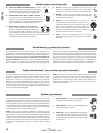
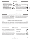
Connect a footswitch to the amplier to remotely enable OVERDRIVE.
Fender makes three footswitch pedals that will work (shown at right with
part numbers). Any generic single-button latching-type footswitch will
work. We recommend the Fender LED FOOTSWITCH (P/N 0994052000)
for best performance. Contact your local Fender dealer to purchase the
Fender footswitch of your choice.
NOTE: If a footswitch is connected, the front panel switch will still work,
but it is possible for its position IN/OUT to become backwards (i.e.
IN=OFF), depending on the footswitch status. The Overdrive light (LED)
on the front panel will ALWAYS be correct, but the LED in the footswitch
may be incorrect. If using a footswitch with an LED, keep the front panel
switch in the OUT position to have the correct status displayed on the
footswitch LED.
1. ECONOMY FOOTSWITCH — (P/N 0994049000) Ba-
sic black one-button on/o footswitch.
2. VINTAGE FOOTSWITCH — (P/N 0994054000)
Chrome one-button on/o footswitch.
3. LED FOOTSWITCH — (P/N 0994052000) Contem-
porary one-button on/o footswitch with LED indi-
cator. NOTE: You must switch the Overdrive eect
o before connecting this footswitch to enable the
footswitch LED to operate properly.
Optional Footswitches
Rear Panel (continued)
FTSW
AUX IN
SEND RETURN
LINE OUT
GROUND LIFT
PHONES
EFFECTS
POWER
ON
OFF
HORN
EXT. SPKR
8
Ω min.
____
W
INPUT POWER
V Hz
______W
______W
ON
OFF
PARALLEL
SPEAKER
OUTPUTS
4Ω min. TOTAL
Your new Rumble head amplifier is lightweight and compact, which
makes it easy to transport and set up. When placed on top of a
non-matching speaker enclosure, however, it becomes subject to the
extreme vibrations it’s capable of producing at high volume (it’s loud!).
Matching Rumble speaker enclosures feature a magnetic locking system
to properly secure a Rumble head amplifier in place during normal
operation. Simply set your Rumble head amplifier into the foot cups on
top of the Rumble speaker enclosure to lock it in place.
NOTE: The magnetic locking system should not be used to secure
your Rumble head amplifier during transportation—we recommend
that you avoid potential damage by first detaching the head from the
Rumble speaker enclosure. Please use caution when using your Rumble
head amplifier on top of any other non-matching speaker enclosure.
Rumble™ Head Amplifiers with Rumble™ Speaker Enclosures
Rumble 200/500 bass amplifiers are equipped with variable speed fan
cooling and thermal shutdown protection. The fan will start at a low
speed and increase as you play harder. Leave at least 6 inches of clear-
ance between the vents on your amplifier and other objects. If the
amplifier vents are blocked, or it is used in an extremely hot environ-
ment, it may overheat and shut down causing a temporary mute of
the speaker while the power LED indicator remains on. Under the most
extreme operating conditions it may be possible for the thermal shut-
down to disrupt the amplifier power supply and the speaker will mute
and the power LED indicator will turn off. If any shutdown (speaker
muting) occurs, leave the power switch ON (to keep the fan running),
and allow the amplifier several minutes to cool down. The amplifier will
automatically resume operation when it has returned to a safe operat-
ing temperature.
Thermal Performance & Protection
ENGLISH