


Installation and Operation, cont’d
DVS 304 • Installation and Operation
2-6
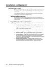
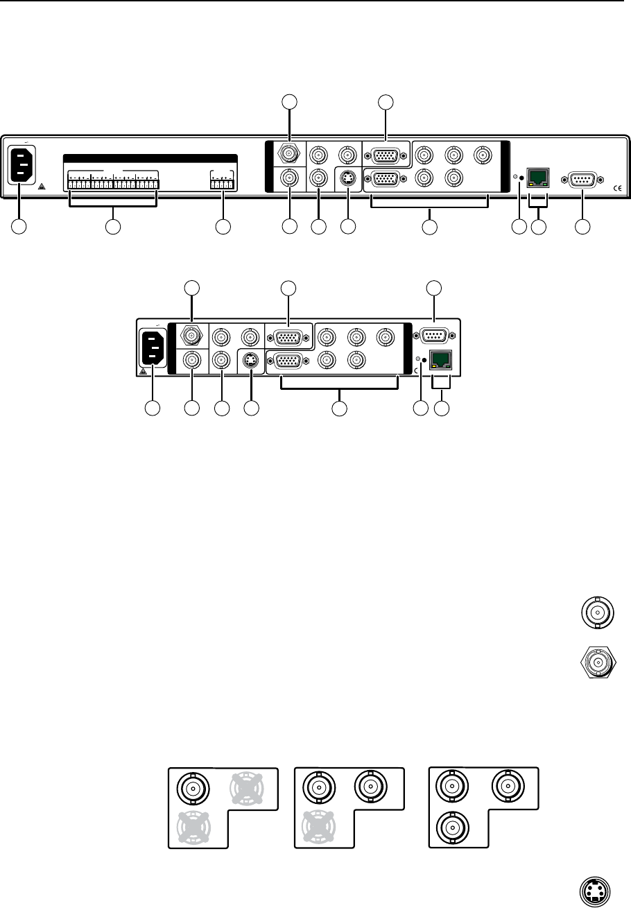
Rear Panel Features
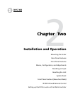
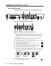
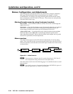
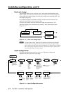
The rear panels of the DVS 304 D and DVS 304 AD models (figures 2-4 and 2-5)
contain all of the possible connectors available on the DVS 304 series of scalers.
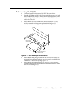
Figure 2-4 — DVS 304 AD rear panel connectors
VID
50/60 Hz
1
2
3
4
Y
/VID
R-Y
H/
HV
R
/R-Y
V
G
/Y
B
/B-Y
RS-232
LAN
RESET
ACTLINK
RGB/R-Y, Y,B-Y
YC
SDI
B-Y
/C
RGB/R-Y, Y,B-Y/YC/VID
100-240V .3A
I
N
P
U
T
O
U
T
P
U
T
4
4a
5
6
9
1
8
11
10
7
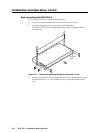
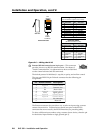
Figure 2-5 — DVS 304 D rear panel power connector
a
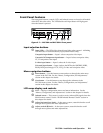
AC power connector — Plug a standard IEC power cord into this connector
to connect the scaler to a 100 to 240 V AC, 50 Hz or 60 Hz power source.
The front panel control and input selection buttons light in sequence during
power-up.
b
Audio input — Plug up to four, 3.5 mm, female, five-pole, captive screw
connectors for balanced/unbalanced variable audio input.
c
Audio output — Plug one, 3.5 mm, female, five-pole captive screw connector
for balanced/unbalanced variable audio output.
d
Video input 1: Composite video — Connect a composite video
signal to this female, BNC connector.
Ü
Optional SDI (serial digital interface) input connector — Connect
an SDI signal to this female BNC connector. During setup, the SDI
input can be assigned to one of the other unused inputs.
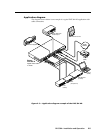
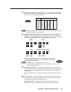
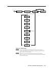
e
Video input 2: Composite/S-video/Component — Connect composite video,
S-video, and component video signals. Connect cables for the appropriate
signal type, as shown here.
Composite Video
2
Y
/VID
B-Y
/C
R-Y
2
R-Y
Y
/VID
B-Y
/C
C
omponent Video (Y, R-Y, B-Y)
2
B-Y
/C
S-video (YC)
Y
/VID
R-Y
f
Video input 3: S-video — Connect an S-video signal to this
4-pin, mini-DIN female connector.
INPUTS OUTPUT
VID
1
2
3
4
Y
/VID
R-Y
H/
HV
R
/R-Y
V
G
/Y
B
/B-Y
RS-232
LAN
RESET
ACTLINK
RGB/R-Y, Y,B-Y
YC
SDI
B-Y
/C
RGB/R-Y, Y,B-Y/YC/VID
I
N
P
U
T
O
U
T
P
U
T
50/60 Hz
100-240V .3A
2
1
3
4
LR
LR
LR
LR
LR
I
N
P
U
T
O
U
T
P
U
T
AUDIO
4
3
7
5
6
9
1
2
11
8
4a
10
1
VID
SDI
3
YC