


5 - 7
5. PARAMETERS
Classifi-
cation
No. Symbol Name and Function
Initial
Value
Unit
Setting
Range
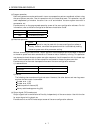
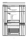
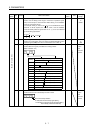
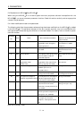
20 INP In-position range
Used to set the droop pulse range in which the in-position signal
(INP) will be output to the controller. Make setting in the feedback
pulse unit (parameter No. 6).
For example, when you want to set
10 m in the conditions that the
ballscrew is direct coupled, the lead is 10mm, and the feedback
pulses are 8192 pulses/rev (parameter No. 6 : 1), set "8" as indicated
by the following expression:
10 10
6
10 10
3
8192 8.192 8
100 pulse 0
to
50000
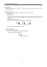
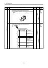
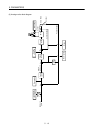
21 MBR Electromagnetic brake sequence output
Used to set a time delay (Tb) from when the electromagnetic brake
interlock signal (MBR) turns off until the base circuit is shut off.
100 ms 0
to
1000
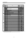
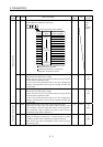
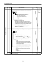
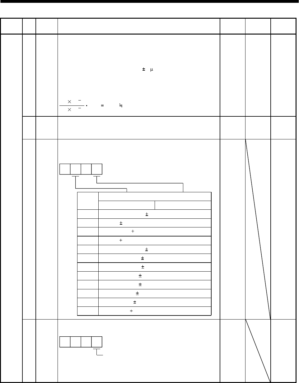
22 MOD Analog monitor output
Used to select the signal provided to the analog monitor.
(Refer to Section 5.3.)
ch1
Setting
0
Analog monitor output selection
Servo motor speed ( 8V/max. speed)
1 Torque ( 8V/max. torque)
2 Motor speed ( 8V/max. speed)
3 Torque ( 8V/max. torque)
4 Current command ( 8V/max. current command)
5 Command speed ( 8/max. speed)
6 Droop pulses ( 10V/128 pulses)
7 Droop pulses ( 10V/2048 pulses)
8 Droop pulses ( 10V/8192 pulses)
9 Droop pulses ( 10V/32768 pulses)
A Droop pulses ( 10V/131072 pulses)
00
B Bus voltage ( 8V/400V)
ch2
0001 Refer to
name
and
function
column.
Adjustment parameters
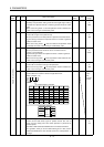
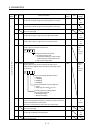
23 *OP1 Optional function 1
Used to make the servo forced stop function invalid.
Servo forced stop selection
0: Valid (Use the forced stop signal (EM1).)
1: Invalid (Do not use the forced stop signal (EM1).)
Automatically switched on internally
000
0000 Refer to
name
and
function
column.