


3 - 2
3. SIGNALS AND WIRING
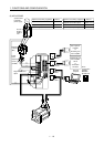
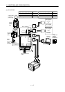
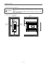
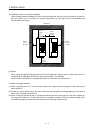
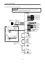
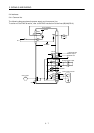
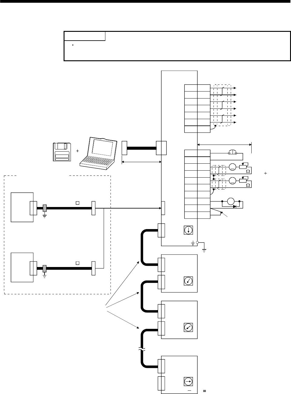
3.1 Connection example of control signal system
POINT
Refer to Section 3.5 for the connection of the power supply system and to
Section 3.6 for connection with the servo motor.
Servo amplifier
(Note 9)
Servo configuration
software
(Note 5)
CN1A
CN1B
(Note 5)
CS1
CN1A
CN1B
CN1A
CN1B
CN1A
CN1B
MR-J2S-B
(2 axis)
CS1
Setting 1
CS1
(Note 11)
CS1
n
(Note 13)
MR-A-TM
A1SD75M(AD75M)
(Note 10, 14) Bus cable
(Note 1)
CN3
(Note 4)
Personal computer
CN3
A
A
CN3
15m(49.2ft)
or less
(Note 5)
Plate
LA
LAR
LB
LBR
SD
LZ
LZR
6
7
16
17
8
18
Encoder A-phase pulse
(differential line driver)
Encoder B-phase pulse
(differential line driver)
Encoder Z-phase pulse
(differential line driver)
EM1
SG
MO1
LG
MO2
LG
SD
MBR
COM
VDD
20
3
4
1
14
11
Plate
13
5
10
(Note 5,8)
2m(6.56ft) or less
(Note 3,4,7)
Forced stop
10k
10k
Monitor output
Max. 1mA
Reading in
both directions
RA1
Magnetic brake
interlock
Setting:0
Servo system controller
MR-J2HBUS M-A
(Option)
Cable clamp
(Option)
or
Motion
controller
(Note 10, 14) Bus cable
MR-J2HBUS M-A
(Option)
Cable clamp
(Option)
(Note 10, 14)
Bus cable
(Option)
MR-J2S-B
(3 axis)
(Note 11)
Setting 2
MR-J2S-B
(n axis)
Setting: n
1
(Note 11)
(Note 12)
1 to 8
Always connect.
(Note 2,6)