


9 - 3
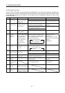
9. TROUBLESHOOTING
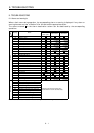
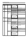
Display Name Definition Cause Action
17 Board error 2 CPU/parts fault
19 Memory error 3 ROM memory fault
Faulty parts in the servo amplifier
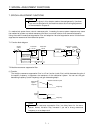
Checking method
Alarm (17 or 19) occurs if power
is switched on after CN1A, CN1B
and CN3 connectors are
disconnected.
Change the servo amplifier.
1A Motor
combination
error
Wrong combination
of servo anplifier
and servo motor.
Wrong combination of servo
amplifier and servo motor connected.
Use correct combination.
1. CN2 connector disconnected. Connect correctly.
2. Encoder fault Change the servo motor.
20 Encoder error 2 Communication
error occurred
between encoder
and servo amplifier.
3. Encoder cable faulty
(Wire breakage or shorted)
Repair or change cable.
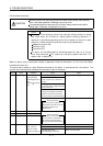
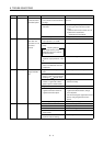
1. Power input wires and servo motor
output wires are in contact at
main circuit terminal block (TE1).
Connect correctly.
2. Sheathes of servo motor power
cables deteriorated, resulting in
ground fault.
Change the cable.
24 Main circuit
error
Ground fault
occurred at the
servo motor outputs
(U,V and W phases)
of the servo
amplififer.
3. Main circuit of servo amplifier
failed.
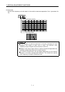
Checking method
Alarm (24) occurs if the servo is
switched on after disconnecting
the U, V, W power cables from
the servo amplifier.
Change the servo amplifier.
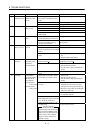
1. Battery voltage lowAbsolute position
data in error
2. Battery cable or battery is faulty.
Change battery.
Always make home position setting again.
25 Absolute
position erase
Power was switched
on for the first time
in the absolute
position detection
system.
3. Super capacitor of the absolute
position encoder is not charged
After leaving the alarm occurring for a few
minutes, switch power off, then on again.
Always make home position setting again.
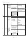
1. Mismatch between used
regenerative brake option and
parameter No. 2 setting
Set correctly.
2. Built-in regenerative brake
resistor or regenerative brake
option is not connected.
Connect correctly
3. High-duty operation or continuous
regenerative operation caused the
permissible regenerative power of
the regenerative brake option to
be exceeded.
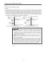
Checking method
Call the status display and check
the regenerative load ratio.
1. Reduce the frequency of positioning.
2. Use the regenerative brake option of
larger capacity.
3. Reduce the load.
4. Power supply voltage is abnormal.
MR-J2S-
B:260V or more
MR-J2S-
B1:135V or more
Review power supply
Permissible
regenerative power
of the built-in
regenerative brake
resistor or
regenerative brake
option is exceeded.
5. Built-in regenerative brake
resistor or regenerative brake
option faulty.
Change servo amplifier or regenerative
brake option.
30 Regenerative
alarm
Regenerative
transistor fault
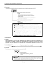
6. Regenerative transistor faulty.
Checking method
1) The regenerative brake option
has overheated abnormally.
2) The alarm occurs even after
removal of the built-in
regenerative brake resistor or
regenerative brake option.
Change the servo amplifier.