


3 - 25
3. SIGNALS AND WIRING
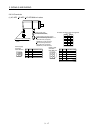
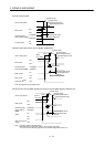
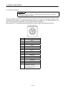
3.11 Control axis selection
POINT
The control axis number set to CS1 should be the same as the one set to
the servo system controller.
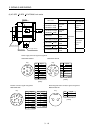
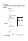
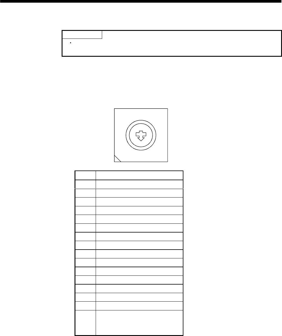
Use the axis select switch (CS1) to set the control axis number for the servo. If the same numbers are set
to different control axes in a single communication system, the system will not operate properly. The
control axes may be set independently of the bus cable connection sequence.
Set the switch to "F" when executing the test operation mode using servo configuration software.
Axis select switch (CS1)
1
C
B
A
9
8
7
6
5
4
3
2
0
F
E
D
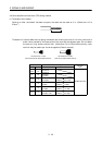
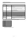
No. Description
0Axis 1
1Axis 2
2Axis 3
3Axis 4
4Axis 5
5Axis 6
6Axis 7
7Axis 8
8 Not used
9 Not used
A Not used
B Not used
C Not used
D Not used
E Not used
F Test operation mode or
when machine analyzer is used
(Refer to Section 6.1.2)