


1
CONTENTS
1. FUNCTIONS AND CONFIGURATION 1- 1 to 1-18
1.1 Introduction.............................................................................................................................................. 1- 1
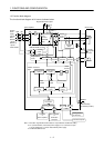
1.2 Function block diagram ..........................................................................................................................1- 2
1.3 Servo amplifier standard specifications ................................................................................................ 1- 3
1.4 Function list ............................................................................................................................................. 1- 4
1.5 Model code definition .............................................................................................................................. 1- 5
1.6 Combination with servo motor............................................................................................................... 1- 6
1.7 Structure................................................................................................................................................... 1- 7
1.7.1 Parts identification........................................................................................................................... 1- 7
1.7.2 Removal and reinstallation of the front cover .............................................................................. 1-11
1.8 Servo system with auxiliary equipment...............................................................................................1-13
2. INSTALLATION 2- 1 to 2- 4
2.1 Environmental conditions....................................................................................................................... 2- 1
2.2 Installation direction and clearances .................................................................................................... 2- 2
2.3 Keep out foreign materials ..................................................................................................................... 2- 3
2.4 Cable stress .............................................................................................................................................. 2- 4
3. SIGNALS AND WIRING 3- 1 to 3-26
3.1 Connection example of control signal system....................................................................................... 3- 2
3.2 I/O signals................................................................................................................................................. 3- 4
3.2.1 Connectors and signal arrangements.............................................................................................3- 4
3.2.2 Signal explanations .......................................................................................................................... 3- 5
3.3 Alarm occurrence timing chart .............................................................................................................. 3- 6
3.4 Interfaces.................................................................................................................................................. 3- 7
3.4.1 Common line ..................................................................................................................................... 3- 7
3.4.2 Detailed description of the interfaces .............................................................................................3- 8
3.5 Power line circuit.................................................................................................................................... 3-11
3.5.1 Connection example......................................................................................................................... 3-11
3.5.2 Terminals.......................................................................................................................................... 3-13
3.5.3 Power-on sequence...........................................................................................................................3-14
3.6 Connection of servo amplifier and servo motor ...................................................................................3-15
3.6.1 Connection instructions ..................................................................................................................3-15
3.6.2 Connection diagram.........................................................................................................................3-15
3.6.3 I/O terminals ....................................................................................................................................3-17
3.7 Servo motor with electromagnetic brake ............................................................................................. 3-19
3.8 Grounding................................................................................................................................................ 3-22
3.9 Servo amplifier terminal block (TE2) wiring method.........................................................................3-23
3.10 Instructions for the 3M connector....................................................................................................... 3-24
3.11 Control axis selection ...........................................................................................................................3-25
4. OPERATION AND DISPLAY 4- 1 to 4- 8
4.1 When switching power on for the first time.......................................................................................... 4- 1