


MCS-D 200 Control Unit
E
08
3. MCS-D 200 Control Unit
The MCS-D 200 control unit is the heart of the system. It controls the delegate, chairman and interpreter microphone stations.
The MCS-D 200 control unit has a modular power supply unit to power a maximum of 15 microphone stations (optional 30). If
more than 30 microphone stations are to be used, additional power supply units are necessary to meet the power requirement.
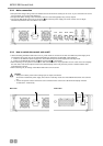
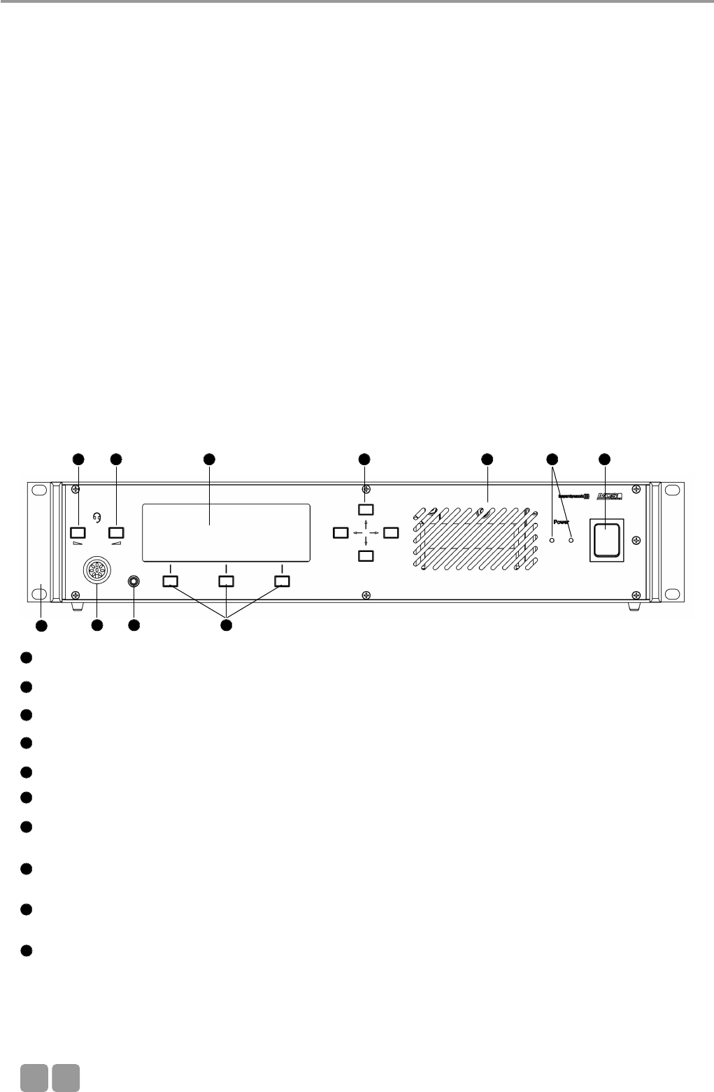
3.1 Controls and indicators
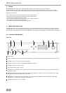
Front view
Power switch
Power on LEDs (the number of illuminated LEDs indicates the number of power supply units integrated into the control unit)
Ventilation grille. Do not cover to avoid overheating.
Socket to connect microphone or headset (8 pin DIN 45326) - inactive
Headphone socket (3.5 mm) - inactive
Volume buttons (left, right) - inactive
Display with 20 characters / 4 lines. Three lines are used for various menu data. The bottom line is used for the description
of the Control Keys.
Navigator buttons (left, right, up, down). Using the navigator bottoms up / down you can scroll through the menu; using
the navigator bottoms left / right you can enter data.
Menu buttons; so-called “hot keys”. Depending on the menu, they act as ENTER, EXIT, VOL-, SETUP, VOL +, SET, LIMIT,
MODE button. The description is displayed in the lower line.
Mounting brackets for 19" rack mounting.
1
2
3
4
5
6
7
8
9
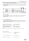
2. Set-up
The MCS-D 200 system may only be installed by staff acquainted with the appropriate safety instructions.
The MCS-D 200 control unit and the power supply units have been developed for installation on tables or 19"-mounting.
Do not cover the ventilating grille. When setting up the system please follow the safety instructions mentioned in chapter 1.
Furthermore, please note
• the ambient temperature of the installation site must not exceed 50 °C.
• there must not be exceeding dust and humidity at the installation site.
• that the unit is not exposed to direct sunlight.
• the connections must be protected against direct access during operation.
• that there must be a strain relief of the cables.
• the installation site must be protected against vibrations.
10
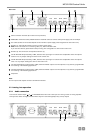
6 6 7 8 3 12
954
10