


CA 4115/30/45 Power Supply Unit
E
42
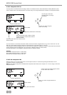
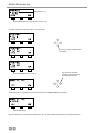
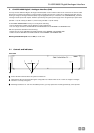
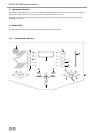
4.2 Connection
4.2.1 Control unit – power supply unit
• The MCS-D 200 control unit and the power supply unit are connected via the NetRateBus socket . Refer also to chapter 8.
“Set-up examples”.
Warning: Connected devices (e.g. adapters or Digital/Analog interfaces) are powered by the MCS-D 200 control unit and
have to be considered in power calculations.
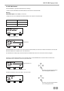
• Each unit which is connected to a NetRateBus socket is powered by the MCS-D 200 when it is switched on. It is not important
if the power supply unit is switched on or off. A Digital/Analog interface or adapter connected to the NetRateBus sockets
would be powered by the power converter of the MCS-D 200. These sockets are not the power outputs for the microphone
stations, adapter or interfaces.
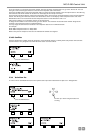
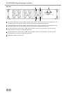
4.2.2 Microphone stations - power supply unit
• Connect microphone stations, Digital/Analog interfaces and adapters to the EXTENSION PORTS angeschlossen.
• Any device which is connected to an EXTENSION PORT, is powered by the power converters 1-3 of the CA 4115/30/45 power
supply unit, when the MCS-D 200 control unit and the power supply unit are switched on. This is indicated by the illuminated
LEDs 1-3.
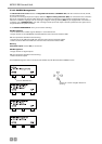
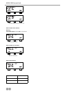
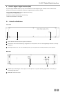
4.3 How to switch on the power supply unit
• Check all connections before switching on.
• Stand-by: A switched-on power supply unit is in stand-by mode when the mains switch is illuminated, but the power
converters 1-3 cannot emit power via the EXTENSION PORTS , because the MCS-D 200 control unit is not yet switched on.
In this case neither the “POWER” LED nor the power converter LEDs 1-3 will illuminate.
• We recommend switching on the devices as described in the following:
1. Switch on all power supply units first. The mains switch will illuminate and indicate the stand-by mode.
2. Switch on the MCS-D 200 control unit. The “POWER” LED of the MCS-D 200 will illuminate.
Then the “POWER” LED of each power supply unit will illuminate.
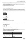
• Then the power converters 1-3 can emit power via the EXTENSION PORTS . The illuminated power converter LEDs 1-3
display the appropriate power supply unit:
LED 1 CA 4115 (1 power converter for 2 A)
LED 1 + 2 CA 4130 (2 power converters for 4 A)
LED 1 + 2 + 3 CA 4145 (3 power converters for 6 A).
• The green Power-LED of the power supply unit will illuminate when the MCS-D 200 control unit is switched on and a bus
signal is produced, no matter if the mains switch of the power supply unit is switched on or off.
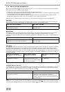
• The LEDs indicate the following:
GREEN: OFF:
- the MCS-D 200 control unit is switched on
- the power supply unit is switched on
- the power converter emits power via the EXTENSION
PORTS
- the MCS-D 200 control unit is switched off
- the power supply unit is switched off
- the power converter is not installed or defective
8
9
9
1
2
2
2 3
9
3
2
1