


41
AXIS Q7401 - Unit connectors
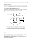
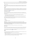
Unit connectors
Network connector - RJ-45 Ethernet connector. Supports Power over Ethernet (PoE). Using shielded cables is recommended.
PoE classification switch - Power over Ethernet (IEEE 802.3af), selectable
power classification:
• Class 2 - max 6.49W
• Class 3 - max 12.95W (default)
Note:
P
ower classification is performed at power up. If the video encoder does not power the connected analog camera,
select PoE Class 2 to inform the PoE switch that the video encoder only needs max 6.49W. PoE Class 3 is the default
setting.
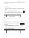
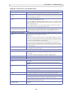
Power connector - 2-pin terminal block used for power input or power output.
• Power input - To supply power to the video encoder with the supplied
power adapter or an external power
supply 8-20V DC, max. 7.2W.
• Power output - the video encoder can supply power to an anal
og camera or auxiliary equipment if powered
by PoE, 12V DC max 5W (420mA).
.
Notes:
•
The video encoder can deliver a maximum of 5W (420mA) with PoE. This includes the output on the power
connector and the I/O terminal connector.
• Do not connect a power supply if the video encoder is connected to PoE.
Audio in - 3.5mm input for a mono microphone, or a line-in mono si
gnal (left channel is used from a stereo signal).
Audio out - Audio output (line level) that can be connected to a public address (
PA) system or an active speaker with a
built-in amplifier. A pair of headphones can also be attached. A stereo connector must be used for the audio out.
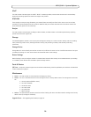
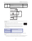
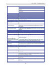
I/O terminal connector - Used in applications for e.g. motion
detection, event triggering,
time lapse recording and alarm notifications. In add
ition to an auxiliary power and a GND pin,
the AXIS Q7401 has 4 pins that can be configured as either input or out put. These pins
provide the interface to:
• Transistor output - For connecting external de
vices such as relays and LEDs. Connected
devices can be activated by AXIS VAPIX API, output buttons on the Live View page or by
an Event Type. The output will show as active (shown under Event Configuration > Port Status) if the alarm device is
activated.
• Digital input - An alarm input for connecting devices that can toggle
between an open and closed circuit, for example:
PIRs, door/window contacts, glass break detectors, etc. When a signal is received the state changes and the input becomes
active (shown under Event Configuration > Port Status.).
Function Pin number Description
GND 1 Ground
DC Power 2 Power input 8-20V DC, max 7.2W or
Power output 12V DC, max 5W (420mA).
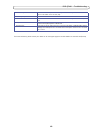
Function Pin number Notes Specifications
GND 1 Ground
12VDC
Powe
r
2 Can be used to power auxiliary equipment.
Notes:
This pin can only be used as power out.
Same voltage as pin 2 of the power connector.
Max load = 100mA
1
2