


Displaying Stream Content
71
MAX-CSE/MAX-CSD10 Operation/Reference Guide
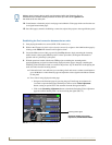
If there is no signal displayed, return to the MAX-CSE UI pages and from the Encoder
Profiles page, confirm that the correct panel IP Address and target port where entered
into the Streaming Source field within the TPDesign4 project.
If this still doesn’t produce a displayed signal, cycle the Play/Stop buttons and verify that
both the encoding Status says Streaming (verifying that the process of encoding is
underway) and that the unit is detecting an incoming signal (shown by the word SYNC
appearing in the Video Sync section of the UI).
The most common error can result from a bad cable not being detected and therefore no
signal becomes available for the unit to encode. The encoding process can continue on a
MAX-CSE even without an actual signal being detected.
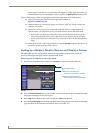
Setting up a Computer to Receive and Display a Stream
The MAX-CSE must first be configured to target a specific computer and a specific set of ports on that
target machine so that the third-party player has content to receive and display on-screen.
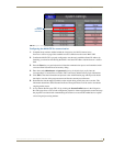
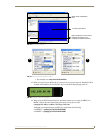
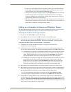
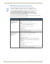
Obtaining the IP Address of the target computer
1.
On your PC, click Start > Run to open the Run dialog.
2. Enter cmd into the Open field and click OK to open the command DOS prompt.
3. From the C:\> command line, enter ipconfig to display the current IP Address of the PC. The
information displayed includes the DNS Suffix, IP Address, Subnet Mask, and Default gateway.
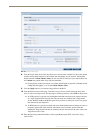
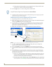
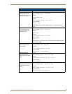
Configure the MAX-CSE for communication to a computer
1.
Complete the first 10 steps described in the previous Configuring the MAX-CSE for
communication section on page 65.
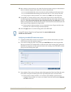
2. From the Stream section of the page, locate the Transport Protocol field and use the drop-down
arrow to select a desired protocol. For the purposes of these procedures, select UDP as the protocol.
An UDP protocol is typically used with higher-bandwidth streams and only requires the entry
of a single Target Port because both the video and audio are combined into a single media
stream. With this method, the user will only need to launch one instance of the third-party
player because BOTH signals are fed into the application as part of the same stream.
An RTP protocol is typically used both with lower-bandwidth streams and when user wants to
purposely separate the video and audio information into two distinct streams. With this
method, the user will only need to launch two instances of the third-party player because
EACH signal is fed to the target computer as its own separate stream. Once instance will
display the video whereas the second instance will provide the corresponding audio.
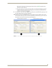
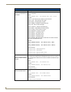
3. Enter the previously obtained IP Address of the target computer into the Target Address field.
4. Enter a numeric value into the Target Port field. This field corresponds to the port on the destination
device where the outgoing video (audio/video) stream is being directed to. It is recommended that
the value being entered is not currently in use by another port on the target device.
It is recommended that the following ports not be used: 21, 22, 23, 80, 443, and 1319.
For the purposes of these procedures, we’ve chosen to use 5000 as the video Target Port.
5. If using RTP as a Transport Protocol, enter a value into the Target Audio Port field. This field
corresponds to the port on the destination device where the audio only portion of the stream is being
directed to. This value can not match the value entered into the Target Port field above. If using
UDP as a Transport Protocol, this field becomes greyed-out and unused since the both the audio and
video content is being combined into a single stream.