


MAX-CSE and MAX-CSD10 Installation
16
MAX-CSE/MAX-CSD10 Operation/Reference Guide
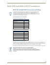
When used for outputs, the I/O port acts as a switch to GND and is rated at 200 mA @
12 VDC. This device can utilize up to 2 I/O ports (see table below).
The PWR pin provides +12 VDC @ 200 mA and is designed as a power output for the PCS2
or VSS2 (or equivalent).
The GND connector is a common ground and is shared by all I/O ports. A common ground is
shared with I/O ports 1 & 2 (see table below)
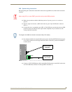
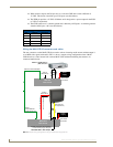
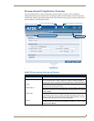
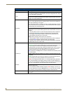
Wiring the MAX-CSD10 connectors and cables
The rear connectors on the MAX-CSD10 are used to take an incoming media stream and then output it
as an RGB video signal (with audio). FIG. 11 shows a sample wiring configuration where a MAX-
CSD10 receives a video stream from a remote MAX-CSE and then distributing the content to its
connected media device.
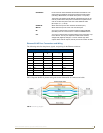
I/O Port Wiring Specifications
Pin Signal Function
1 GND Signal GND
2 I/O 1 Input/Output
3 I/O 2 Input/Output
4 12 VDC PWR
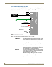
FIG. 11
Sample wiring configuration using a CSD10 and a target device
(BNC)
Audio In
(Stereo RCA)
via Ethernet
Direct PWR
Connection
MAX-CSD10
Video Decoder
Power
supply
Outbound Audio/Video/Data
or
(S-Video)
MAX-CSE
Video Encoder
Audio In
(Stereo RCA)
via Ethernet (RJ-45)
Direct PWR
Connection
Inbound
MAX-CSD10
Video Decoder
RGB Video Out
(BNC)
(S-Video)
Audio/Video/Data
White - Left Channel
Red - Right Channel
The BNC connector can be adapted
to use an RCA plug by using the
INCLUDED BNC to RCA Adapter.
(to target device)
or
Power
supply
S-Video or COMP Video In
(DVD, VCR, etc.)