


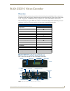


MAX-CSE and MAX-CSD10 Installation
13
MAX-CSE/MAX-CSD10 Operation/Reference Guide
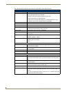
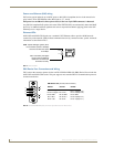
Ethernet/RJ-45 Port: Connections and Wiring
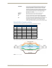
The following table lists the pinouts, signals, and pairing for the Ethernet connector.
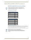
FIG. 6 diagrams the RJ-45 pinouts and signals for the Ethernet RJ-45 connector and cable.
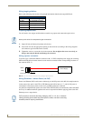
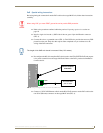
•ETHERNET: RJ-45 connector routes streamed Audio/Video and Data out to an
external device capable of receiving the streamed media content
(including a MAX-CSD10, VG-Series touch panel, or computer).
The Power-over-Ethernet (PoE) feature of the Ethernet port can be
used to provide indirect DC power to this 802.3af-compliant device
over the unused wire pairs in the UTP or STP Ethernet cable
(RJ-45 pins 4, 5, 7, and 8).
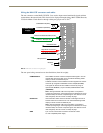
• AUDIO IN: Stereo line-level input via two rear RCA connectors (R/L).
• MIC IN: Stereo line-level input via a rear 1/8” mini-stereo jack.
•IR: 2-pin 3.5 mm mini-Phoenix connector accepts a single IR Emitter
(CC-NIRC) and can connect one IR- or Serial-controllable device.
• I/O: 4-pin 3.5 mm mini-Phoenix connector allows for the connection of up
to two devices. The I/O port responds to either switch closures,
voltage level (high/low) changes, or can be used for logic-level
outputs. When used for outputs, the I/O port acts as a switch to GND.
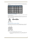
Ethernet RJ-45 Pinouts and Signals
Pin Signals Connection
s
Pairing Color
1 TX + 1 --------- 1 1 --------- 2 Orange-White
2 TX - 2 --------- 2 Orange
3 RX + 3 --------- 3 3 --------- 6 Green-White
4 no connection 4 --------- 4 Blue
5 no connection 5 --------- 5 Blue-White
6 RX - 6 --------- 6 Green
7 no connection 7 --------- 7 Brown-White
8 no connection 8 --------- 8 Brown
FIG. 6
RJ-45 wiring diagram