


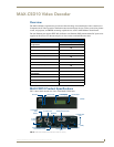


MAX-CSE and MAX-CSD10 Installation
9
MAX-CSE/MAX-CSD10 Operation/Reference Guide
MAX-CSE and MAX-CSD10 Installation
MAX-CSE and MAX-CSD10 Connections and Wiring
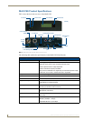
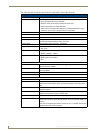
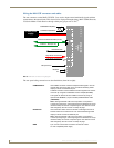
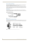
Port Assignments and Functionality
The rear Port Assignments are as follows:
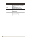
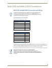
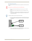
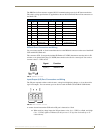
Wiring Guidelines - Direct Power
The MAX-CSE and MAX-CSD10 units require the use of either an external 12 VDC-compliant power
supply or an 802.3af-compliant device to provide DC power. Power can be fed to the unit through either
the rear 2-pin 3.5mm mini-Phoenix PWR connector or the rear Ethernet connector (PoE).
Use the power requirements from the Specifications table on page 2 to determine the unit’s power draw.
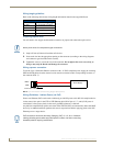
The MAX CSE and MAX-CSD10 are configured to be used as standalone units
running on a network capable of supporting the up to a 6Mbps data rate. It is
recommended that you set up the unit locally prior to installing it within an AC-RK
19-inch rack unit, as described on page 17.
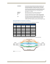
MAX-CSE Port Assignments
Description ICSP Port #
Video Encoder 1
RS-232/422/485 (DB9) Serial Port 2
IR/Serial Port 3
I/O Port 4
IR RX Port 5
LCD Display 6
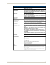
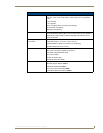
MAX-CSD10 Port Assignments
Description ICSP Port #
Video Decoder 1
RS-232/422/485 (DB9) Serial Port 2
IR/Serial Port 3
I/O Port 4
IR RX Port 5
LCD Display 6
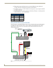
This unit should only have one source of incoming power.
Although the unit can be connected to two separate power sources, the
12 VDC-compliant power input overrides the PoE. Refer to the Wiring Guidelines -
Indirect Power (via PoE) section on page 10 for specific PoE wiring procedures and
restrictions.