


MAX-CSE and MAX-CSD10 Installation
15
MAX-CSE/MAX-CSD10 Operation/Reference Guide
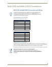
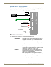
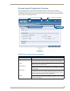
The DB9 Device Port connector supports RS-232 communication protocols for PC data transmission.
This table’s wiring specifications are applicable to the rear RS-232/422/485 Device Port connectors on
the MAX-CSE.
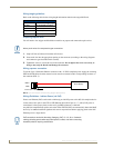
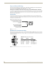
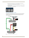
IR/Serial Port: Connections and Wiring
You can connect one IR- or Serial-controllable device to the IR/Serial connector on the rear of the MAX-
CSE and MAX-CSD10 units.
This connector (FIG. 9) accepts the included IR Emitter (CC-NIRC) that mounts onto the device's IR
window, or an optional mini-plug (CC-NSER) that connects to the device's control jack. You can also
connect a data 0 - 5 VDC device.
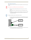
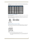
Input/Output (I/O) Port: Connections and Wiring
The I/O port responds to either switch closures, voltage level (high/low) changes, or it can be used for
logic-level outputs. You can connect up to two devices each on MAX-CSE and MAX-CSD10 units.
A contact closure between the GND and an I/O port is detected as a Push.
When used for voltage inputs, the I/O port detects a low (0 - 1.5 VDC) as a Push, and a high
(2.0 - 3.3 VDC) signal as a Release (this IO port uses 3.3V logic but can handle up to 5V
without harm).
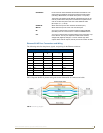
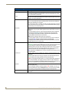
RS-232/422/485 Device Port Wiring Specifications
Pin Signal Function RS-232 RS-422 RS-485
1 RX- Receive data X X (strap to pin 9)
2 RXD Receive data X
3 TXD Transmit data X
4 TX+ Transmit data X X (strap to pin 6)
5 GND Signal ground X X
6 RX+ Receive data X X (strap to pin 4)
7 RTS Request to send X
8 CTS Clear to send X
9 TX- Transmit data X X (strap to pin 1)
FIG. 9
IR/SERIAL connector
FIG. 10 INPUT/OUTPUT connector
IR
Signal: Function:
GND (-) Signal GND
Signal (+) IR/SERIAL data
+12V
GND
I/O
I/O
I/O