


MAX-CSE and MAX-CSD10 Installation
14
MAX-CSE/MAX-CSD10 Operation/Reference Guide
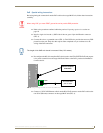
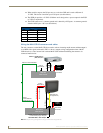
Power over Ethernet (PoE) wiring
PoE can be used to indirectly provide DC power to this 802.3af-compliant device via the unused wire
pairs in the UTP or STP Ethernet cable (RJ-45 pins 4, 5, 7, and 8).
PoE power is overridden if a direct power feed (via the rear 2-pin PWR connector) is detected.
Any 802.3af-compliant PoE switch (such as the NXA-ENET24 PoE) can automatically detect the MAX
device by its authenticated PoE signature and sense its required load before applying power to the PoE
Ethernet port on a target device.
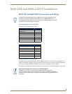
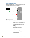
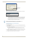
Ethernet LEDs
MAX-CSE and MAX-CSD10 units use a standard CAT5 Ethernet cable to provide 10/100 network
connectivity to the network. LEDs indicate communication activity, connection status, speeds, and mode
information as described in FIG. 7.
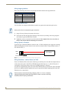
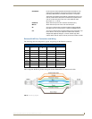
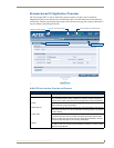
DB9 Device Port: Connections and Wiring
FIG. 8 shows the connector pinouts for the rear RS-232/RS-422/RS-485 (DB9) Device Port on both the
MAX-CSE and MAX-CSD10 units. This port supports most standard RS-232 communication protocols
for data transmission.
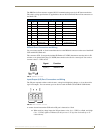
FIG. 7 Ethernet LEDs
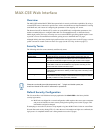
FIG. 8 RS-232/422/485 DB9 (male) connector pinouts for the rear Device Port
SPD
L/A
ETHERNET 10/100
SPD
- Speed LED lights (yellow) when
and turns Off when the speed
is 10 Mbps.
the connection speed is 100 Mbps
L/A
- Link/Activity LED lights
(green) when the Ethernet
cables are connected and
terminated correctly.
5
4
3
2
1
9
8
7
6
Male
DB9 Device Port pinouts (male connector)
Pin 2: RX signal
Pin 3: TX signal
Pin 5: GND
Pin 7: RTS
Pin 8: CTS
RS-232
Pin 1: RX -
Pin 4: TX +
Pin 5: GND
Pin 6: RX +
Pin 9: TX -
RS-422
Pin 1: A (strap to 9)
Pin 4: B (strap to 6)
Pin 5: GND
Pin 6: B (strap to 4)
Pin 9: A (strap to 1)
RS-485