


MAX-CSE and MAX-CSD10 Installation
11
MAX-CSE/MAX-CSD10 Operation/Reference Guide
PoE - Special wiring instructions
Before beginning the connection from the PoE switch to the target MAX unit, follow these instructions
carefully:
Refer to the procedures outlined within the previous Preparing captive wires section on
page 10.
Install a single wire into the (-) GND side of the rear green 2-pin mini-Phoenix connector
(FIG. 4).
Connect this wire to a grounded source (FIG. 4). This GND wire provides the necessary ESD
protection to the unit. Only after this step has been completed can you continue on to the
wiring of the PoE connection.
Pre-configure the 802.3af-compliant PoE switch (such as the NXA-ENET24 PoE) and prepare
it for power transmission to the target MAX unit. Refer to the PoE’s product documentation
for more details.
Connect a CAT5/CAT6 Ethernet cable from the RJ-45 PoE connector on the PoE switch to the
rear RJ-45 (Ethernet) connector on the target MAX unit (FIG. 4).
When using PoE, you must FIRST ground the unit to provide ESD protection.
The length of the GND wire should not exceed 6 feet (1.83 meters).
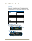
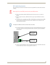
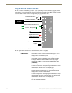
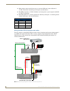
FIG. 4 ESD grounding and PoE connection of a MAX unit
PWR +
GND -
Grounded Metal
plate or object
MAX-CSE
R
E
A
R
802.3af-compliant
PoE switch
EthernetPWR
MAX-
CS
E