75-EN
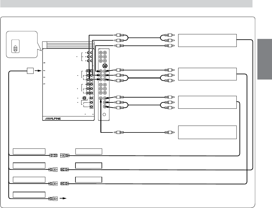
When Connecting External Equipment
SUB W.
REAR
FRONT
Ai-NET
L
R
VIDEO
CAMERA IN
(MONO)
L
AUX IN 3
R
RADIO ANTENNA IN
REMOTE IN/OUT
NAVIGATION IN
DISPLAY OUT
POWER SUPPLY
VIDEO
AUDIO
(MONO)
L
AUX IN 1/2
R
AUDIO
VIDEO
L
AUX OUT
R
AUDIO
1
2
1
2
3
PRE IN/OUT
NORM
EQ/DIV
1
REMOTE IN(AUX1)
IVA-D901
Tuner BOX
REMOTE IN(AUX2)
REMOTE OUT
REMOTE OUT
REVERSE
2
3
5
6
4
8
8
8
7
9
8
REMOTE OUT(AUX3)
REMOTE IN
!
!
To Audio Input terminal
Rear monitor 1
(Sold Separately)
To Video Input terminal
To Video Input terminal
To Audio Input terminal
To Audio Output terminal
To Video Output terminal
To Video Output terminal
Rear monitor 2
(Sold Separately)
TV Tuner or VCR
(Sold Separately)
Back-up camera
(Sold Separately)
(White/Brown)
(White/Brown)
(White/Brown)
(White/Brown)
(Orange/White)
Use only when back-up camera is connected.
1 System Switch
When connecting an equalizer or divider using Ai-NET
feature, place this switch in the EQ/DIV position. When no
device is connected, leave the switch in the NORM
position.
• Be sure to turn the power off to the unit before changing the
switch position.
2 Remote IN/OUT Terminal
3 AUX Video/Audio Output (AUX2) Terminal
Use when connecting an optional monitor etc.
4 AUX Video/Audio Output (AUX1) Terminal
Use when connecting an optional monitor etc.
5 AUX Video/Audio Input (AUX3) Terminal
6 CAMERA Input Terminal
Use when connecting a back-up camera.
7 Remote Control Output Lead (White/Brown)
Connect this lead to the remote control input lead. This
lead outputs the controlling signals from the remote
control.
(White/Brown)
8 RCA Extension Cable (Sold separately)
9 Connect to the plus side of the car's reverse lamp
which lights when the transmission is shifted into
reverse (R).
Switches the video picture to the back-up camera.
This is linked to putting the car into reverse (R).
! Remote Control Input Lead (White/Brown)
(White/Brown)


