


33 En
Connections
PREPARATION
l ADAPTIVE DRC indicator
Lights up when the adaptive dynamic range control
feature is turned on (page 95).
m Decoder indicators
The respective indicator lights up when any of the
decoders of this unit function.
n Tuner indicators
Light up when this unit is in the FM, AM, XM Satellite
Radio, or SIRIUS Satellite Radio tuning mode.
The HD and TAG indicators are only applicable to the U.S.A.
model and used when this unit is tuned into the HD Radio
reception band.
o Menu browsing indicator
Lights up if any items exist under the current item during
menu browsing for iPod, etc.
p SLEEP indicator
Lights up while the sleep timer is on (page 45).
q PRE AMP indicator
Lights up when this unit is in the pre-amplifier mode
(page 131).
r VOLUME level indicator
• Indicates the current volume level.
• Flashes while the mute function is on (page 44).
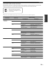
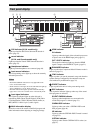
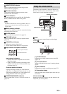
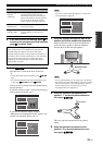
s Input channel and speaker indicators
Input channel indicators
• Indicate the channel components of the current
digital input signal.
• Light up or flash according to the settings of the
speakers when this unit is in the automatic setup
procedure (page 35).
Presence speaker indicators
Light up according to setting for “Front Presence”
(page 93) in “Configuration” when this unit is in the
auto setup procedure (page 35) or the speaker level
setting procedure in the “Level” (page 94).
t ZONE2/ZONE3/ZONE4 indicators
Lights up when Zone 2, Zone 3, or Zone 4 is turned on
(page 127).
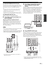
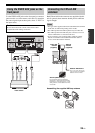
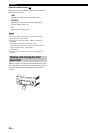
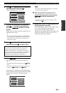
The remote control transmits a directional infrared ray.
Be sure to aim the remote control directly at the remote
control sensor on this unit during operation.
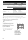
6LIGHT
Lights up the remote control buttons and the display
window (4).
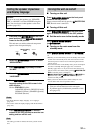
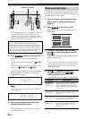
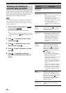
Display window (4)
[1] ID1/ID2 indicator
Indicates the currently selected remote control ID
(page 130).
[2] Transmit indicator
Appears while the remote control is sending infrared
signals.
[3] Zone indicators
Indicates the currently controlling zone (page 127).
[4] Information display
Shows the name of the selected input source that you
can control.
Infrared window (1)
Outputs infrared control signals. Aim this window at the
component you want to operate.
Note
L C R
SL LFE SR
SBL SB SBR
Presence speaker indicators
Input channel indicators
Using the remote control
MASTER
MAIN ZONE
INPUT
ON
OFF
MIC
OPTIMIZER
AUDIO
SELECT
SPEAKERS
AB
YPAO
SILENT CINEMA
PHONES
ON/OFF
PURE DIRECT
VOLUME
MULTI
ZONE
STRAIGHTTUNING MODE
ZONE ON/OFF
MENU
TONE CONTROL
ZONE
CONTROLS
REC OUT/
ZONE 2
MEMORY FM/AM
EDIT
PRESET/TUNING
EFFECT DISPLAY
MAN'L/AUTO
CATEGORY
SEARCH MODE
PUSH ENTER
PROGRAM
R
L
OPTICAL
HDMI IN USB
AUDIO
VIDEO AUX
S VIDEO
VIDEO
ZONE 3 ZONE 4
ZONE 2
30 30
Approximately 6 m (20 ft)
Remote control sensor
MAIN
ZONE 2
ID 2ID 1
ZONE 3
ZONE 4
[1] [2]
[3] [4]