


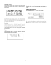
Matrix Settings
There are four options to set in this screen. Any changes
in these settings requires the power of the beltpack and
the base station to be reset.
The settings are the following:
Display Call
Enable - (Default) All incoming calls
appear in the call waiting display.
Disable - LED flashes until caller releases key.
Key Flash
Enable - (Default) 15 second flash after incom-
ing call is received.
Disable - LED flashes until caller releases key.
Latch Keys
Enable - Latching is turned on.
Disable - (Default) Latching turned off.
Matrix Address
Intercom ports are arranged in groups of eight.Within
each group, a keypanel is uniquely identified by its
address switch setting. Set the number of the RKP-4 sys-
tem here. Valid selections are 1 - 8.
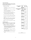
Four Wire Settings
This screen provides the ability to set the following:
.
4W input and output audio levels
.Auxiliary ON/OFF
.
Auxiliary input and output audio levels
.
Relay ON/OFF
The 4W input and output levels referred to in this section are
those at the matrix RJ-12 connector. The Relay button on the belt-
pack also has the added selectable options of relay latching or
non-latching.
Setting the 4-Wire, Aux and Relay Options
1. From the status screen hit <MENU> one to arrive at the
security code / system settings / four wire settings / RF
meter menu screen.
2. Select the four wire settings menu with the <UP> /
<DOWN> arrow keys and press <SET> to go to the set-
ting’s screen.
3. The 4W input level will be flashing. Select the desired
level by using the <UP> / <DOWN> arrow buttons then
pressing <SET>. The 4W output level will now be flash-
ing.
4. Select the desired output level by using the <UP> /
<DOWN> arrow buttons then pressing <SET>. The aux
Yes or No option will now be flashing.
5. Use the <UP> / <DOWN> arrow keys to select aux input
audio Yes or No. Press <SET> to accept the choice.
6. If aux input was set to “Y” then the user will be asked to
set the auxiliary input and output levels. Use the <UP> /
<DOWN> arrow keys to adjust the input and output lev-
els, then press <SET> to accept the levels. The Relay
option will now be flashing.
7. To enable the relay function the “RLY”letters should be
setting to normal by using the <UP> / <DOWN> arrow
buttons then press <SET>. To disable the relay set the
“RLY” to inverted letters then press <SET>.
8. Press <MENU> to go back to the status screen, press
<SET> to continue editing options at the beginning of the
screen.
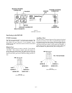
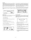
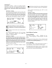
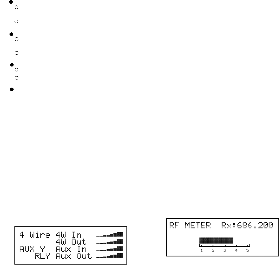
RF Meter
This screen displays a larger version of the 5 bars of received
signal strength displayed on the status screen. It also displays
the receive frequency.
Changing to the RF meter screen
1. From the status screen hit <MENU> once to arrive at
the security code / system settings / four wire settings
/ RF meter menu screen.
2. Select the RF meter menu with the <UP> / <DOWN>
arrow keys and press <SET> to go to the RF meter.
6-8